7. Interrupt Handling
154
PowerSpan II User Manual
80A1010_MA001_09
Integrated Device Technology
www.idt.com
7.5
DMA Interrupts
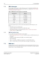
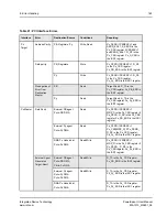
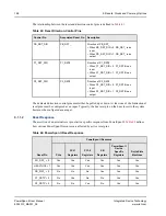
The PowerSpan II DMA supports a number of interrupt sources for each channel. Individual enable
and status bits exist for each source. The status and enable bits are contained in the
Control and Status Register” on page 314
:
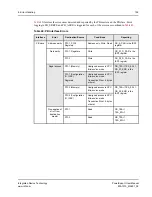
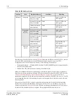
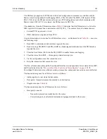
The following programming steps route done, halt and stop interrupts on DMA channel two onto
INT[3]_:
•
Set the DMA2_EN bit in the IER0 register
•
Program the DMA2_MAP bit to 0bx101 in the IMR_DMA register
•
Set the DONE_EN, HALT_EN, STOP_EN bits in the
“DMA x General Control and Status
(DMAx_GCSR)
7.5.1
DMA Interrupt Servicing
To service a DMA interrupt, the following steps must be taken:
•
Read
“Interrupt Enable Register 0” on page 332
(ISR0) to determine which DMA channel caused
the interrupt
•
Read DMAx_GCSR to determine which DMA source caused the interrupt
•
Service the interrupt
•
Write 1 to clear DMAx_GCSR[
status_bit
] and allow a restart of the DMA channel
•
Write 1 to clear the DMAx_EN bit in the ISR0 register and negate the interrupt signal
7.6
Mailboxes
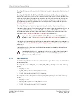
PowerSpan II provides eight 32-bit general Mailbox registers for passing messages between processes.
Each Mailbox has an associated interrupt enable and status bit. When enabled, an interrupt is generated
whenever there is a write to the Mailbox register.
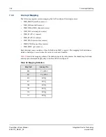
Table 39: DMA Channel Interrupt Sources and Enables
Interrupt Source
Enable bit
DONE
DONE_EN
P1_ERR
P1_ERR_EN
P2_ERR
P2_ERR_EN
PB_ERR
PB_ERR_EN
HALT
HALT_EN
STOP
STOP_EN

