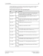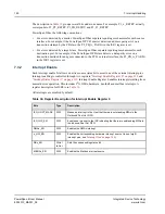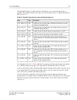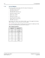
8. Error Handling
158
PowerSpan II User Manual
80A1010_MA001_09
Integrated Device Technology
www.idt.com
•
Error logging registers that capture parameters from the transaction that caused the error
•
Assertion of external bus protocol pins
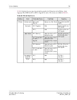
PowerSpan II has separate reporting mechanisms for each source port when errors are detected by
a master. For example, if the PC1-2 Master detects a address parity error on a transaction claimed
by the PB slave, the P2_PB_A_PAR bit in the ISR1 register is set.
For errors detected by a target/slave, PowerSpan II provides separate reporting tools for each
destination port. For example, if the PowerSpan II PB slave detects a data parity error on a
transaction destined for an agent connected to the PCI-1 external interface, the PB_P1_D_PAR bit
in the ISR1 is set.
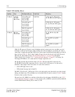
Each PowerSpan II DMA channel provides an additional reporting mechanism (see
).
8.2
PB Interface Errors
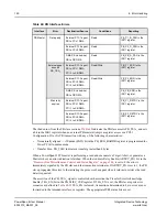
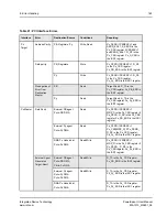
The PB master and slave detect error conditions while participating in PB transactions. In addition to
Interrupt Status Register 1, the PB Interface has the following error reporting mechanisms:
•
Assertion of PB_TEA_
—
provided the Transfer Error Acknowledge Enable (TEA_EN) bit in the
“Processor Bus Miscellaneous Control and Status Register” on page 304
(PB_MISC_CSR) is set
to 1
•
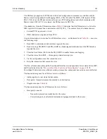
Capture of specific parameters from the transaction that caused the error
a.
“Processor Bus Error Control and Status Register” on page 302
(PB_ERRCS) logs:
–
PB_TT signals
–
PB_TSIZ signals
b.
“Processor Bus Address Error Log” on page 303
(PB_AERR) logs:
–
PB_A signals


