background image

DMK 33UX183 Technical Reference Manual

14

Camera Controls

UVC drivers see it with the 

FourCC


Y800

.

The 

Device Driver for The Imaging Source USB 33U, 37U and 38U Cameras

 offers this

pixel format as the 

Y800

 video format.

5.1.1.2

12-Bit Packed Monochrome

This format transmits data using 3 bytes for each pair of 2 consecutive pixels.

USB3 Vision

 drivers see this pixel format as 

Mono12p

.

UVC drivers see it with the 

FourCC


Y12p

.

The 

Device Driver for The Imaging Source USB 33U, 37U and 38U Cameras

 offers this

pixel format as the 

Y16

 video format. Since the DMK 33UX183 camera offers both 12-

bit packed and 16-bit monochrome pixel formats, the driver will use the 12-bit packed
format when the 

Y16

 video format is selected.

5.1.1.3

16-Bit Monochrome

The sensor of the DMK 33UX183 camera is not capable of providing 16-bit data output.
Instead, the pixel data is transmitted in the most significant bits which allows
application programs to ignore the sensor-specific data type, and treat the data as if
the sensor outputs 16 bits.

USB3 Vision

 drivers see this pixel format as 

Mono16

.

UVC drivers see it with the 

FourCC


Y16

.

The 

Device Driver for The Imaging Source USB 33U, 37U and 38U Cameras

 offers this

pixel format as the 

Y16

 video format.

5.1.2

Resolution

The DMK 33UX183 allows the user to specify which rectangular region of the image
sensor to read out during camera operation. The size of this rectangle determines the
number of pixels that have to be transferred for each frame and has a significant
influence on the required USB bandwidth.

Lowering the resolution also often allows the image sensor to operate at a higher frame
rate. Changes in the vertical resolution have more effect on the maximum frame rate
than changes in the horizontal direction.

The way the resolution is controlled varies greatly between the driver technology used
to access the camera:

·

When using 

USB3 Vision

, the resolution is controlled through the GenICam features

Width and Height.

·

When using the uvcvideo on Linux, the resolution is selected from a list of fixed
formats. Dynamic frame sizes are not available.

·

When using 

IC Imaging Control

, the resolution is part of the video format, a parameter

that combines pixel format, resolution and readout mode. For more information, refer

Summary of Contents for DMK 33UX183

Page 1: ...DMK 33UX183 Technical Reference Manual...

Page 2: ...13 5 1 Sensor Readout Control 13 Pixel Format 13 5 1 1 8 Bit Monochrome 13 5 1 1 1 12 Bit Packed Monochrome 14 5 1 1 2 16 Bit Monochrome 14 5 1 1 3 Resolution 14 5 1 2 Readout Modes 15 5 1 3 Frame Ra...

Page 3: ...6 1 General Purpose Output 28 5 6 2 5 7 Strobe 28 Strobe Enable 28 5 7 1 Strobe Polarity 29 5 7 2 Strobe Operation 29 5 7 3 Strobe Duration 30 5 7 4 Strobe Delay 30 5 7 5 5 8 Image Processing 30 Gamm...

Page 4: ...ical Interface IR Cut filter No Sensor Type Sony IMX183CLK J Shutter Type Rolling Sensor Format 1 inch Pixel Size 2 4 m Lens Mount C CS Electrical Interface Interface USB 3 0 Supply voltage 4 75 VDC t...

Page 5: ...83 Technical Reference Manual 5 Quick Facts Environmental Temperature operating 5 C to 45 C Temperature storage 20 C to 60 C Humidity operating 20 to 80 non condensing Humidity storage 20 to 95 non co...

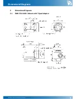
Page 6: ...DMK 33UX183 Technical Reference Manual 6 Dimensional Diagrams 2 Dimensional Diagrams 2 1 DMK 33UX183 C Mount with Tripod Adapter...

Page 7: ...DMK 33UX183 Technical Reference Manual 7 Dimensional Diagrams 2 2 DMK 33UX183 C Mount without Tripod Adapter...

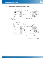
Page 8: ...DMK 33UX183 Technical Reference Manual 8 Dimensional Diagrams 2 3 DMK 33UX183 CS Mount with Tripod Adapter...

Page 9: ...DMK 33UX183 Technical Reference Manual 9 Dimensional Diagrams 2 4 DMK 33UX183 CS Mount without Tripod Adapter...

Page 10: ...n c 5 n c 6 n c 7 GND_I O G3 External Ground 8 n c 9 n c 10 STROBE_OUT O3 Open drain 24 01 V 11 TRIGGER_IN I3 Optocoupler signal 3 32 24 02 V 12 TRIGGER_IN I3 Optocoupler ground 1 max 0 2A ID for open...

Page 11: ...olled The current input signal can also be read directly through the General Purpose Input feature 3 1 2 STROBE_OUT The STROBE_OUT line s main usage is to indicate the integration time of the image se...

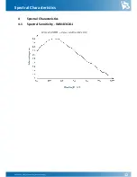
Page 12: ...DMK 33UX183 Technical Reference Manual 12 Spectral Characteristics 4 Spectral Characteristics 4 1 Spectral Sensitivity IMX183CLK J...

Page 13: ...n the pixel format is controlled through the PixelFormat GenICam feature When using the uvcvideo driver on Linux the pixel format is defied by video4linux2 When using IC Imaging Control the pixel form...

Page 14: ...Vision drivers see this pixel format as Mono16 UVC drivers see it with the FourCC Y16 The Device Driver for The Imaging Source USB 33U 37U and 38U Cameras offers this pixel format as the Y16 video fo...

Page 15: ...pixel during readout The nature of this merge operation is sensor specific most sensors either add the pixel values or average them Generally binning modes provide better image quality than skipping...

Page 16: ...maging Control the frame rate is selected from a list of available frame rates through APIs such as Grabber setFPS or ICImagingControl DeviceFrameRate The range of available frame rates depends upon o...

Page 17: ...s actually read out can be specified by the Partial Scan Offset X and Partial Scan Offset Y parameters By default the camera automatically positions the offsets so that the center of the sensor is use...

Page 18: ...nICam OffsetAutoCenter Video4Linux2 ROI Auto Center VCD Property VCDID_PartialScanOffset VCDElement_PartialScanAutoCenter 5 1 6 Image Flipping The DMK 33UX183 camera allows for vertical flipping of th...

Page 19: ...mplification that is applied to the image at sensor level Parameter Gain Minimum 0 dB Maximum 2704 dB Default auto USB3 Vision GenICam Gain Video4Linux2 Gain db 100 VCD Property VCDID_Gain VCDElement_...

Page 20: ...to controlled parameters For example one might want to avoid high gain settings in order to keep noise levels low Other applications require limiting the maximum exposure time so that movements do not...

Page 21: ...10 12 16 bit output images and a tone mapping algorithm in post processing when using higher bit depths as the dark areas still contain a lot of useful information Parameter Highlight Reduction True...

Page 22: ...possible value for the current frame rate Parameter Auto Exposure Upper Limit Auto On Select Auto Exposure Upper Limit automatically Off Let the user control Auto Exposure Upper Limit USB3 Vision GenI...

Page 23: ...enables the trigger mode Parameter Trigger Mode On Enable Trigger Mode True Off Disable Trigger Mode False USB3 Vision GenICam TriggerMode Video4Linux2 Trigger Mode VCD Property VCDID_Trigger VCDElem...

Page 24: ...et Release mode USB3 Vision GenICam TriggerOperation Video4Linux2 Trigger Operation VCD Property VCDID_Trigger VCDElement_TriggerOperation 5 4 4 Software Trigger The Software Trigger function can be u...

Page 25: ...ggerSource 5 4 7 Trigger Overlap The Trigger Overlap feature gives information on when a new trigger pulse is accepted in the trigger exposure readout sequence Parameter Trigger Overlap Off The next t...

Page 26: ...ger function are not delayed by this parameter Parameter Trigger Delay Minimum 0 s Maximum 1 s Default 0 s USB3 Vision GenICam TriggerDelay Video4Linux2 Trigger Delay VCD Property VCDID_Trigger VCDEle...

Page 27: ...Time Minimum 0 s Maximum 1 s Default 0 s USB3 Vision GenICam TriggerDenoise Video4Linux2 Trigger Noise Suppression Time VCD Property VCDID_Trigger VCDElement_TriggerDenoise 5 6 Digital I O The 33U ser...

Page 28: ...arameter controls the status of the STROBE_OUT pin Parameter General Purpose Output True Drive the STROBE_OUT line high 1 False Drive the STROBE_OUT line low 0 USB3 Vision GenICam GPOut Video4Linux2 G...

Page 29: ...exposure time True ActiveLow The STROBE_OUT pin is logically low during the exposure time False USB3 Vision GenICam StrobePolarity Video4Linux2 Strobe Polarity VCD Property VCDID_Strobe VCDElement_St...

Page 30: ...5 Strobe Delay The Strobe Delay parameter can be used to add a small delay between the start of exposure and the strobe output pulse Parameter Strobe Delay Minimum 0 s Maximum 32767 s USB3 Vision GenI...

Page 31: ...e is applied only to the Y channel In bayer raw and RGB24 modes all color channels are subject to the same lookup operation The lookup table has 257 16 bit entries The upper 8 bits of the image data a...

Page 32: ...9 Region of Interest for Auto Functions The 33U series cameras allow for the setting of a region of interest that is used while controlling the Auto Exposure Auto Gain and Auto White Balance function...

Page 33: ...OI Preset VCD Property VCDID_AutoRoi VCDElement_AutoRoiPreset 5 9 3 Auto Functions ROI Custom Rectangle When Auto Functions ROI Preset is set to Custom Rectangle the user can manually set the position...

Page 34: ...can be saved into and restored from one of two available memory slots upon user s request Additionally the camera can be configured to load one of the user s camera configurations at startup 5 10 1 U...

Page 35: ...Parameter Save User Set Execute Save the current camera configuration into the memory slot specified by User Set Selector USB3 Vision GenICam UserSetSave 5 10 4 Default User Set The Default User Set p...

Page 36: ...DMK 33UX183 Technical Reference Manual 36 Revision History 6 Revision History Date Version Description 2018 10 15 Initial release of this document...

Page 37: ...g Source Company reserves the right to make changes in specifications function or design at any time and without prior notice Last update November 2018 2018 The Imaging Source All rights reserved Repr...

Reviews: