background image

ÊÀÑÊÎÄ

9

CANPC527D

Chapter 3 - Hardware discription describes the major features of the CANPC527D: the Intel 82527
CAN bus controller, Galvanic isolation of the CAN-bus.

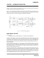
Figure 3-1 shows the general block diagram of the CANPC527D. This chapteer describes the major
features of the CANPC527D: the Intel 82527 CAN-bus controller, Galvanic isolation of the CAN-bus,
the Fiberoptic interface, the Onboard configuration EEPROM, and Digital I/O.

        Fig. 3-1. CANPC527D Block diagram

82527 CAN bus controller

Reference note:

(Intel publication CAN Architectural Overview, Automotive Products Databook)

The 82527 CAN controller consists of six functional block. The CPU interface logic manages the
communication to the host computer. The CAN controller interface to the CAN bus and implements the
protocol rules of the CAN protocol for the transmission and reception of messages. The RAM is the
physical interface layer between the host CPU and the CAN bus. One eight bit I/O port provides low
speed I/O capabilities.

The 82527 RAM provides storage for 15 message objects of 8 byte length. Each message object has a
unique identifier and can be configured to either transmit of to receive except for the last message object.
The last message object is a receive-only buffer with a special mask design to allow selected groups of
different message identifiers to be received.

Each message identifier contains control and status bits. A message object with a direction set for receive
will send a remote frame by requesting a message transmission. A message set as transmit will be configured
to automatically send a data frame whenever a remote frame with a matching identifier is received over the
CAN bus. All message objects have separate transmit and receive interrupt and status bits, allowing the
CPU full flexibility in detecting when a remote frame has been sent or received.

CHAPTER 3 - HARDWARE DESCRIPTION

Summary of Contents for CANPC527D

Page 1: ...CANPC527D Isolated 1 Mb s Full CAN Interface Board User s Manual KASKOD 1999 Sankt Peteterburg...

Page 2: ...189625 S Petrsburg Pavlovsk Filtrovskoy road 3 tel 812 466 5784 476 0795 Fax 812 465 3519 E mail cascod online ru kaskod spb cityline ru http www kaskod ru...

Page 3: ...vanicisolationoftheCANbus 8 CHAPTER 4 BOARD OPERATION AND PROGRAMMING 9 Definingthememorymap 9 Interrupts 9 Whatisaninterrupt 9 Interruptrequestlines 9 8259Programmableinterruptcontroller 9 Interruptm...

Page 4: ...and remote frames as follows A Programmable Global Message Identifier Mask 15 message objects of 8 byte Data Length and a Programmable Bit Rate This fully integrated chip supports all the functinalit...

Page 5: ...s channel 2 then J3 What commes with your board YouwillreceivethefollowingitemsinyoueCANPC527Dpackage lCANPC527D CAN bus interface module l Software diskette with C source code for CAN bus interfacing...

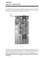
Page 6: ...ram in the beginning of this chapter Fig 1 CANPC527D contains 2 identical optoisolated CAN 2 0B specification channels First chan nel registers begin from base address the second base address 100h Eac...

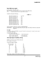
Page 7: ...possible range setting is 080000h 0FFE00h Explanation BoardstartsworkingwhenaddresslinesignalA19issethigh Connectioncorresponds tohighlevel Examples To set base address 0C8000h connect 21 and 22 in Se...

Page 8: ...at incompatible jumper settings can result in unpredictable board operation and erratic response Generalinstallationguidelines 1 Turn OFF the power to your computer and all devices connected to CANPC5...

Page 9: ...the transmission and reception of messages The RAM is the physical interface layer between the host CPU and the CAN bus One eight bit I O port provides low speed I O capabilities The 82527 RAM provid...

Page 10: ...age object 15 the local mask allows a large number of infrequent messages to be received by the 82527 Message object 15 is also buffered to allow the CPU time to service a message received Galvanic is...

Page 11: ...hen returns to what it was doing beforetheinterruptoccurred OthercommondevicesthatuseinterruptsareNetworkboards A Dboards serial ports etc Your CANPC527D can interrupt the main processor when a messag...

Page 12: ...m especiallywhenprogramming under DOS The following discussion will cover programming under DOS Note that even the smallest mistakeinyourinterruptprogrammaycausethecomputertohangupandwillonlyrestartaf...

Page 13: ...is problem such as those which involve checkingifanyDOSfunctionsarecurrentlyactivewhenyourISRiscalled butsuchsolutionsare beyond the scope of this manual The second major concern when writing ISR s is...

Page 14: ...e installing and initializing your ISR To mask the IRQ read the current IMR at I O port 21h and set the bit that corresponds to tout IRQ the IMR is arranged so that bit 0 is for IRQ0 and bit 7 for IRQ...

Page 15: ...interrupt new_IRQ1_handler void Function init_irq_handlers Inputs Nothing Returns Nothing Purpose Set the pointers in the interrupt table to point to our functions ie setup for ISR s void init_irq_han...

Page 16: ...bus connector CAN Interface Galvanicallyisolatedtransceiverwith1Mb sdatarate Timingparametersandspeedofbusprogrammable Balanced CAN bus choke for low EMI emissions Jumper selectable 120 Ohm onboard te...

Page 17: ...available There are many CAN related system development packages Hardware interface cards and easy to use softwarepackagesprovidesystemdesigners buildersandmaintainerswithawiderangeofdesign moni torin...

Page 18: ...design or in service Industrial Applications of CAN CAN controllers and interface chips are physically small They are available as low cost off the shelf components Theywilloperateathigh real timespe...

Page 19: ...nown as Basic CAN and Full CAN The terms Basic CAN and Full CAN must not be confused with the terms Standard CAN the 11 bit identifier or Version 2 0A data format and Extended CAN the 29 bit identifie...

Page 20: ...message and thus its content is relevant to that particular node If the message is relevant it will be processed otherwise it is ignored Identifiers The unique identifier also determines the priority...

Page 21: ...likely that the more rapidly changing parameters need to be transmitted more frequently and there fore mustbegivenahigherpriority To cater for real time data communication this requires not only a fas...

Page 22: ...message contains a 15 bit Cyclic Redundancy Check CRC code The CRC is com puted by the transmitter and is based on the message content All receivers that accept the message performasimilarcalculationa...

Page 23: ...sarelikelytobecausedbybadconnec tions faultycables defectivetransmittersorreceivers orlonglastingexternaldisturbances The general principle only is described here More detailed information is availabl...

Page 24: ...tal number within the code word is odd The residual undetected error probability of the CRC check alone is 3 x 10 to the power 5 Inconjunctionwithalltheothererrorcheckingmechanisms amorerealisticvalue...

Page 25: ...of seven recessive bits FollowingtheEndOfFrameistheINTermissionfieldconsistingofthreerecessivebits After the three bit INTermission period the bus is recognised to be free Bus Idle time maybe of any a...

Page 26: ...essages Theywill also acknowledge receipt of 2 0B messages but then ignore them Therefore within the above mentioned constraints it is possible to use both Version 2 0A with 2 0B passive capabilities...

Page 27: ...ta long Phase seg2is themaximumofPhase seg1 and the Information Processing Time where the Information Processing Time is less than or equal to 2 time quanta Synchronisation When any node receives a da...

Reviews: