Section 4: Pulse card concepts
Model 4200A-SCS Pulse Card (PGU and PMU) User's Manual
4-22
4200A-PMU-900-01 Rev. A December 2020
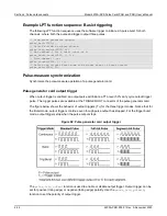
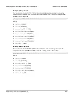
Example LPT function sequence: Basic triggering
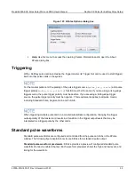
The following LPT function sequence uses the software trigger to initiate a 3-pulse burst for both
channels, where both the pulse and trigger output three pulses.
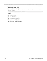
// Stop pulse generator output:
pulse_halt(VPU1);
// Select software trigger source:
pulse_trig_source(VPU1, 0);
// Set channel 1 for a burst count of 3:
pulse_burst_count(VPU1, 1, 3);
// Turn channel 1 on:
pulse_output(VPU1, 1, 1);
// Select the trigger burst mode and trigger start of burst output:
pulse_trig(VPU1, 2);
Pulse-measure synchronization
Synchronize the pulse-measure operation of a pulse generator card.
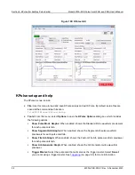
Pulse generator card output trigger
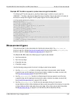
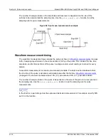
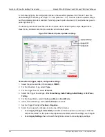
When output trigger is enabled, an output pulse will initiate a TTL-level, 50% duty cycle output trigger
pulse. The trigger pulses are available at the TRIGGER OUT connector of the pulse generator card.
The figure below shows the behavior of output triggers (T
O
) for the three trigger modes. Notice that for
the Burst mode, output triggers continue even though pulse output has stopped. For the trigger burst
mode, output triggers stop when the pulse output stops.
Figure 92: Pulse generator card output trigger
The
pulse_trig_output
function is used to enable or disable output trigger. Output trigger can be
set for positive (rising edge) or negative (falling edge) polarity. Use the
pulse_trig_polarity
function to set the polarity of output trigger.

