background image


PIC Frisbee 

www.kitronik.co.uk


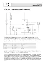
Three of the outputs have been connected to LEDs. Between each of the PIC outputs and each of 

the LEDs is a resistor. The purpose of these resistors is to limit (restrict) the flow of current into the LEDs. 

This controls the brightness of the LED and prevents it from becoming damaged, which would 
happen if no resistor was used. A 330

 resistor has been used for this purpose. 


The circuit has been designed so that a buzzer can be added. The type of buzzer used should not 
have any drive circuitry. This means that it needs driving with square wave (alternating high low 

voltage signal) to make it produce a tone. The frequency of the tone will be the same as that of the 

square wave that is used to drive it. It is by varying this tone that the sounder can be used to play a 
musical tune. 


One other point worth noting is the processor clock. For any micro-controller to work it requires a clock 
source. The micro-controller uses this clock so that it knows when to execute the next line of software.  

Often these clocks are generated externally but in the chip used in this circuit the clock is built into the 

chip itself. This is why it does not appear on the circuit diagram. 
 

Why use a PIC micro-controller? 

There are a number of advantages of using a micro-controller; some of these are outlined below: 


Complex functionality can be produced a very low cost. 


Circuit size can be very small for and still provide complex functionality. 


It is very easy to make minor alterations to the function of the product. 

o


For instance changing the tune that is played. 


Flexibility. The circuit could easily be used for a completely different function by simply re-

writing the software. 


Easy to develop and debug. Most software packages allow you to simulate the software while 

it is being developed making it much more likely to work when used. It is also possible to break 

the functionality down into small steps which is easier to get right then jumping straight to the 
final design. 

Summary of Contents for PIC Frisbee

Page 1: ...PIC Frisbee Build Instructions Issue 1 1 ...

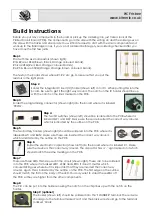
Page 2: ... soldered into the PCB where it is labeled SW1 and SW2 Make sure these are inserted the correct way around which is indicated by the outline on the PCB Step 5 The two battery holders shown right should be soldered into the PCB where it is labeled BAT1 and BAT2 Make sure these are inserted the correct way around which is indicated by the outline on the PCB Step 6 Solder the electrolytic capacitor s...

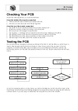
Page 3: ...the outlines on the PCB Testing the PCB The circuit has been designed to allow easy testing of the PCB To test the PCB you will first have to insert a chip programmed with some software to allow it to be tested The purpose of the test program is to test that the LEDs work the buzzer can sound if fitted and that the switches are functioning used to turn the LED and buzzer patterns on and off The te...

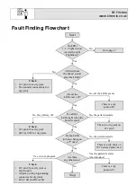
Page 4: ... they all stay off Check IC1 pin 4 for a dry joint SW1 SW2 for dry joints No Stop Yes Go to page 2 Yes No all the LEDs are on Do all the LEDs light when the board is spun No the pattern restarts Yes There is a dry joint on IC1 pin 8 No the pattern restarts There is a dry short on IC1 between pins 3 4 Are there any other issue No Yes it wont program Yes the pattern restarts when knocked Check IC1 p...

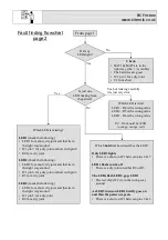
Page 5: ... a dry joint or short with pin 8 R4 for a dry joint LED2 check the following LED2 for a short dry joint and that its in the right way around IC1 pin 6 for a dry joint or short with pin 5 R5 for a dry joint LED3 check the following LED3 for a short dry joint and that its in the right way around IC1 pin 3 for a dry joint R6 for a dry joint Yes From page1 Which bold text best describes the LED Only L...

Page 6: ...hile it is waiting to see if the switches have closed This will give a battery life of around 2 weeks If the sleep function this turns off a lot of the functions within the PIC for around 2 seconds is used it is possible to get the current the circuit uses down to around 0 140mA This will mean the battery life will increase to about 3 months To do this you will need to add the following operations...

Page 7: ...O0 LED1 Output Pin 5 GPIO2 Sounder The other connections to the PIC are to provide it with power V pin 1 and Gnd pin 8 and also allow it to be programmed with the user defined software Pins 2 and 7 When pin 7 is not being used to program the device it is used as the output which controls LED1 The input is connected to the two tilt switches and a resistor When either or both of these switches are o...

Page 8: ...work it requires a clock source The micro controller uses this clock so that it knows when to execute the next line of software Often these clocks are generated externally but in the chip used in this circuit the clock is built into the chip itself This is why it does not appear on the circuit diagram Why use a PIC micro controller There are a number of advantages of using a micro controller some ...

Reviews: