COMe-mAL10 – User Guide, Rev. 1.3
www.kontron.com
// 57
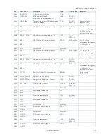
Sub-Screen
Function
Second level Sub-Screen / Description
Miscellaneous>
(continued)
Reset Button
Behavior>
Selects reset button behavior
[Chipset Reset, Power Cycle]
I2C Speed>
Selects internal I2C bus speed between (1 kHz and 400 kHz)
For a default system 200 kHz is an appropriate value.
On-board I2C
Mode>
Keep ‘Multimaster’ setting unless otherwise noted
[MultiMaster, BusClear]
Manufacturing
Mode>
Read only field
Function is disabled
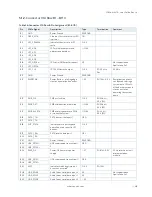
LID Switch
Mode>
Shows or hides Lid Switch Inside ACPI OS
[Enabled, Disabled]
Sleep Button
Mode>
Shows or hides Sleep Button inside ACPI OS
[Enabled, Disabled]
SMBus device
ACPI Mode
Hides the SMBus device from OS if set to hidden, otherwise device is
visable
[Hidden, Normal]
CPLD device
ACPI mode
Hides CPLD device from OS if set to hidden, otherwise device is visible
[Hidden, Normal]
SDIO/GPIO
Output>
Output of SDIO/COMe-GPIO
[Enabled, Disabled]
SDIO/GPIO
Mode>
Selects SDIO or COME-GPIO Mode
[SDIO, COME-GPIO]
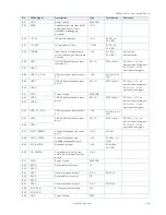
H/W Monitor>
CPU
Temperature>
Read only field
CPU temperature (°C) and Module temperature (°C)
Module
Temperature>
Read only field
Module temperature (°C)
CPU Fan –
Fan Control>
Sets CPU Fan Control mode
Disable - stops fan.
Manual – manually sets the fan
Auto – Hardware monitor controls cooling, similar to ACPI based
‘Active Cooling’, without producing a software load to the system.
[Disabled, Manual, Auto]
CPU Fan –
Fan Pulse>
Displays number of pulses the fan produces during one revolution.
(Range: 1-4)
CPU Fan –
Fan Trip Point>
Displays temperature at which the fan accelerates.
(Range: 20°C – 80°)
CPU Fan –
Trip Point
Speed>
Displays Fan speed at trip point in %. Minimum value is 30 %.
Fan always runs at 100 % at (TJmax.-10°C).
CPU Fan – Ref.
Temperature>
Determines temperature source used for automatic fan control
[Module Temperature, CPU Temperature]
Additional Information CPU Temperature
The CPU temperature value is taken from a thermal resistor (NTC) that is placed very close
to the CPU. The NTC resistor is not capable of measuring very fast rises and falls in
temperature and measurements show a certain non-linearity. The NTC thermal resistor
gives a general indication of the temperature close to the CPU. If the NTC thermal resistor
value is compared to internal CPU values (i.e. DTS based values) certain differences are
expected. These differences are due to the design and are not a bug. The thermal resistor
method was chosen because the CPU does not support PECI based temperature


