8
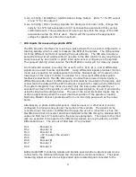
either the appropriate M-code or the operator turns on the spindle with the “button” on
the control screen. The hardware control sequence is as follows: The Mach3 control
turns on either a CW or CCW relay. Then the IO6 sends an appropriate 0-10 volt
analog signal out to the Variable Frequency Drive (VFD) which controls the spindle
motor speed. Finally, the Mach3 control measures and monitors the Spindle RPM by
measuring the pulse rate of a pulse stream that it receives through the IO6 from a
sensor or encoder mounted on the spindle, and displays the RPM on the Mach3 control
panel display.
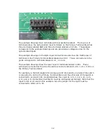
Interfacing the Spindle is accomplished either through the two mod jack connectors 7
and 8 or through Phoenix screw terminal connections to the IO6. For convenience, the
mod jack connections are preferred, and will be discussed first in this section. All of
the signals mentioned and used in the mod jack connections correspond to the
connections that can be made using the screw terminal connections.
4.
IO6 CW and CCW relay outputs
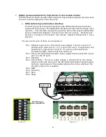
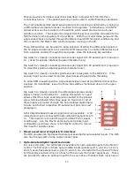
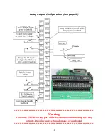
Mod Jack #8 of the 8 mod jack module is dedicated to spindle output signals. See
page 6 Figure 5. All of the connections to the mod jack are also available on phoenix
screw terminals (See page 7 Figure 6), but mod jack connections are made available
for convenience. The relay contacts are rated at 1 amp 115 VAC, and 3 amps at 30
VDC. These relay contacts can be connected to turn on a power contactor for the
spindle motor or for VFD inputs to control direction of rotation. The pin-out of mod
jack # 8 are as follows:
Pin 1
0-10 VDC analog signal for VFD spindle speed control.
Pin 2
CW spindle dry relay contact.
Pin 3
CW spindle dry relay contact.
Pin 4
Enable - voltage provided at external enable voltage supply (EXN)
This will be the same as terminal SOV on the Auxiliary Terminal Block.
Pin 5
GND (for analog voltage on pin 1 and the enable voltage.
Pin 6
No Connection.
Pin 7
CCW spindle dry relay contact.
Pin 8
CCW spindle dry relay contact.
5.
I06 analog spindle voltage output
The Mach3 control software program provides a variable frequency pulse output on a
step signal line which is scalable through the configuration menus in Mach3. This
signal is converted to a proportional analog 0-10 volt signal which is typically used to
control the speed of Variable Frequency Drives (AKA inverters). The hardware on the
IO6 board performs this conversion. The setup to implement this function is
configured in the Mach3 configuration tables. The setup procedure is provided below.
6.
Configuring the 0-10V analog output
1. In Mach3 go to Config / Ports&Pins / Motor Outputs. Enable the spindle and set the
step pin to 1 and step port to 2. Set the DIR pin to 14 and Port2.
3.
Go to Config / Ports&Pins / Spindle setup / motor control. Check the box for “Use
Spindle Motor Output” and check the box for Step /Dir Motor.
Summary of Contents for IO6 V4.0
Page 2: ...2 This page was intentionally left blank...
Page 24: ...21...

