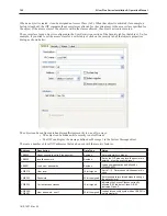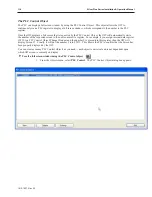
registers monitored on screen. The PLC block pack # represents the maximum number of ‘skips’ between registers
allowed before the OIT considers a PLC register to be part of a different block.
For example, suppose we wish to monitor the following 7 PLC registers on one screen: %R1, %R2, %R4, %R7,
%R12, %R14 and %R100.If PLC block pack is set to 0, the OIT sends seven separate commands to get the data. If
PLC block pack is set to 1, the OIT checks the spacing between requested registers. If the spacing is more than 1,
then a separate command is sent. In this example, the OIT sends four commands- one command to read R1, R2, and
R4; one command to read %R7, one command to read %R12 and %R14, and one command to read %R100.
With most PLC protocol drivers, more time is spent with ‘overhead’ data than getting the actual data that you need.
With the example above, setting the block pack number to 1 probably reduces the time required to update the PLC
data by as much as 40%! So properly setting the PLC block pack can have a major impact on the update rate of the
OIT.
If the PLC block pack setting were adjusted to 4 or greater, the OIT sends only two commands- one command to
read %R1, %R2, %R4, %R7, and %R12; and another command to get %R100. The update rate is now probably
three times as fast!
You might think that the best setting is 10 so why not have the PLC block pack always on 10? However, in some
situations, a setting of 10 may actually slow down the update rate. For example, if the PLC registers displayed on
the screen are actually %R1, %R10, and %R40 with the PLC block pack is set to 10, the OIT will send two
commands: one to get %R1 and %R10, another to get %R40. If the PLC block pack were set to 0, then the OIT
would have sent three commands. In this case, however, the three commands probably take less time than the two
commands because the OIT has to receive data for ten registers (%R1-%R10) in one command takes more time than
the overhead associated with two commands. Therefore, you should experiment with this setting if you find that the
update rate is longer than you would like.
Now that you know your way around EZware-5000 and its various applications, it is time to start creating your own
project. The next seven chapters show you in detail, all of the features that you can use to create a user-friendly
touchscreen graphics operator interface terminal. Along the way, we will attempt to provide you with clear
definitions of each feature and, if necessary, some additional examples of how each feature might be used.
Au to mat i cally Re boot OIT
EasyBuilder can automatically reboot the OIT after download.
4
To enable automatic reboot of OIT after download
1.
From the Tools menu, select
Download
. The Download dialog box is displayed.
2.
Check the
Reboot HMI after download
checkbox.
3.
Click
OK
.
Save and Com pile the Pro ject
EasyBuilder can automatically save and compile the project when downloading or simulating.
4
To enable automatic save and compile
1.
From the Option menu, select
Function Property
. The
Function Property
dialog box is
displayed.
2.
Check the
Automatic save and compile when download and simulate
checkbox.
3.
Click
OK
to exit the
Function Property
dialog box.
1010-1007, Rev 05
104
Sil ver Plus Se ries In stal la tion & Op er a tion Man ual
Summary of Contents for Silver Plus Series
Page 20: ...1010 1007 Rev 05 16 Silver Plus Series Installation Operation Manual ...
Page 31: ...COM Ports for the HMI5056 5070 1010 1007 Rev 05 Connect the OIT to the PLC or Controller 27 ...
Page 38: ...1010 1007 Rev 05 34 Silver Plus Series Installation Operation Manual ...
Page 49: ...7 Click the Shape tab 1010 1007 Rev 05 Creating Your First Project 45 ...
Page 62: ...1010 1007 Rev 05 58 Silver Plus Series Installation Operation Manual ...
Page 75: ...3 Click OK The System Parameter Settings dialog appears 1010 1007 Rev 05 Using EZware 5000 71 ...
Page 132: ...1010 1007 Rev 05 128 Silver Plus Series Installation Operation Manual ...
Page 156: ...1010 1007 Rev 05 152 Silver Plus Series Installation Operation Manual ...
Page 210: ...1010 1007 Rev 05 206 Silver Plus Series Installation Operation Manual ...
Page 216: ...1010 1007 Rev 05 212 Silver Plus Series Installation Operation Manual ...
Page 246: ...1010 1007 Rev 05 242 Silver Plus Series Installation Operation Manual ...

