MAX32600 User’s Guide
Communication Peripherals
7.2 SPI
–
•
Interrupt Servicing:
Status and Control used by an application either directly or via the Peripheral Management Unit’s DMA to efficiently service SPI data
transfer.
–
–
–
7.2.4.1
Static Configuration
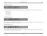
Static configuration should be performed while the SPI port is disabled. Static configuration includes:
• Slave Select signal polarity
• Slave Ready (Flow Control) signal polarity
Slave select polarity is independently configurable for each slave select line for a given SPI port. To set the Slave Select for the SPI port to an Active High State,
set the
field to 0000001b in the register
. To set additional slave selects for the same port, set the appropriate bit(s) in the
field to match the slave select line. By default, the slave selects are set to Active Low.
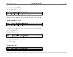
For the slave ready polarity, each slave ready input signal for a given SPI port is configured in the same manner as the Slave Select. Set the
bit in the
register to either a 1 or a 0.
7.2.4.2
Dynamic Configuration
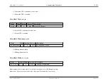
To begin communicating with a given slave device it is necessary to set up several parameters specific to that slave. All of these settings are controlled by the
register.
The
field determines which slave select pin is active during the transaction. A total of five possibilities exist for each SPI Port as
determined by the GPIO mapping and the user configuration and design.
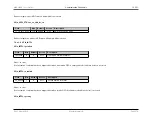
If the slave device only supports 3-Wire mode, setting
to 1 puts the SPI Port into 3-Wire mode. For this mode, the corresponding
output pin SDIO[0] is used for both MOSI and MISO.
Clock Polarity and Phase (Mode Selection)
To select one of the
four supported SPI Modes of operation
, the
field is used. By default, SPI Mode 0 is selected, spi_mode = 00b. The
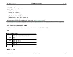
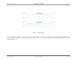
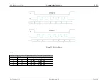
upper bit of spi_mode is used to control the clock polarity. The figure below shows the two different clock polarity settings and how the settings affect the SPI clock
output.
Rev.1.3 April 2015
Maxim Integrated
Page 264

