MAX32600 User’s Guide
Analog Front End
8.3 ADC
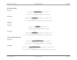
Scan Mode
PGA Bypass
adc
_
sl p
_
cnt
=
f
target
f
PCLK
−
(
N
scan
−
1
)(
pga
_
trk
_
cnt
+
adc
_
acq
_
cnt
+
7
)
−
adc
_
acq
_
cnt
−
24
f
S
= (
N
scan
−
1
)(
pga
_
trk
_
cnt
+
adc
_
acq
_
cnt
+
7
) +
adc
_
sl p
_
cnt
+
adc
_
acq
_
cnt
+
24
×
f
PCLK
PGA Enabled
adc
_
sl p
_
cnt
=
f
target
f
PCLK
−
N
scan
×
(
pga
_
trk
_
cnt
+
pga
_
acq
_
cnt
+
adc
_
acq
_
cnt
+
8
)
−
32
f
S
= (
N
scan
)
×
(
pga
_
trk
_
cnt
+
pga
_
acq
_
cnt
+
adc
_
acq
_
cnt
+
8
) +
adc
_
sl p
_
cnt
+
32
×
f
PCLK
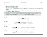
Scan Mode with Burst/Decimation
PGA Bypass
adc
_
sl p
_
cnt
=
f
target
f
PCLK
−
(
2
adc
_
brst
_
cnt
×
N
scan
)
−
1
)(
pga
_
trk
_
cnt
+
adc
_
acq
_
cnt
+
7
)
−
adc
_
acq
_
cnt
−
24
f
S
=
(
2
adc
_
brst
_
cnt
×
N
scan
)
−
1
(
pga
_
trk
_
cnt
+
adc
_
acq
_
cnt
+
7
) +
adc
_
sl p
_
cnt
+
adc
_
acq
_
cnt
+
24
×
f
PCLK
PGA Enabled
adc
_
sl p
_
cnt
=
f
target
f
PCLK
−
2
adc
_
brst
_
cnt
×
N
scan
×
(
pga
_
trk
_
cnt
+
pga
_
acq
_
cnt
+
adc
_
acq
_
cnt
+
8
)
−
32
f
S
=
2
adc
_
brst
_
cnt
×
N
scan
×
(
pga
_
trk
_
cnt
+
pga
_
acq
_
cnt
+
adc
_
acq
_
cnt
+
8
) +
adc
_
sl p
_
cnt
+
32
×
f
PCLK
8.3.4.9
Start the Measurement
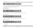
To begin taking measurements, two register fields must be set.
When
is 0, data collection begins when the the CPU ADC data collection start register,
, is set to 1. This is
an active high start signal that starts the programmed data collection sequence when set to 1. It is self-clearing.
When
is 1, the ADC data collection will start when Pulse Train 15 is high. Care must be take in the pulse train programming to ensure
that Pulse Train 15 is low before the ADC collection is complete or the collection process will restart.
8.3.5
Registers (ADC)
8.3.5.1
Module ADC Registers
Rev.1.3 April 2015
Maxim Integrated
Page 422


