DL7, DL7L
70
19 MODBUS RTU / MODBUS TCP TRANSMISSION PROTOCOL
19.1 Insights
The device utilises the following Modbus functions:
03
(0x03)
Read Holding Registers,
04
(0x04)
Read Input Registes
,
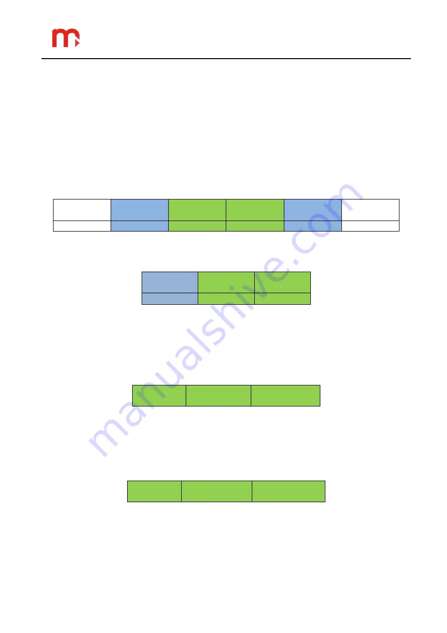
In compliance with the Modbus RTU standard, the frame (information sent) is in the form
of:
Start
Address
Function
Data
CRC
control
End
T1 ... T4
1 byte
1 byte
n bytes
2 bytes
T1 ... T4
In compliance with the MODBUS standard, the frame (information sent) in TCP/IP mode
is in the form of:
MBAP
Header
Function
Data
7 bytes
1 byte
n bytes
Information sent from the master computer to the device is in the form of Queries,
whereas the device itself sends Responses.
19.2 Functions
Functions 03 (0x03) and 04 (0x04) are applied conversely to obtain the register data.
Command 03 or 04 is in the form of:
Function
(1B)
Initial address
(2B)
Number of
registers (2B)
Function
– 03 HEX or 04 HEX – register data reading.
Initial address - address of the register from which data will be sent.
Number of registers
– number of 2 byte registers to read.
In response, the device will send a string of characters in the form of:
Function
(1B)
Number of
bytes (1B)
Data sequence
(nB)
Function
– return confirmation; in the case of an error, 80 HEX is added to the command
code value.
Number of bytes
– n bytes sent in response (instead of the number of registers).
Data
– n bytes of register content.


