Page 85
Appendix | EtherCAT Documentation
optoNCDT 1900 / EtherCAT
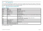
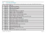
A 5.3.1.11 Object 1C32h: Synchronization Manager Input Parameters
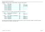
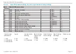
see description of input parameters, see Chap.
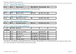
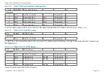
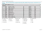
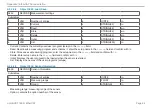
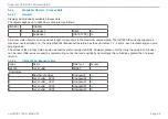
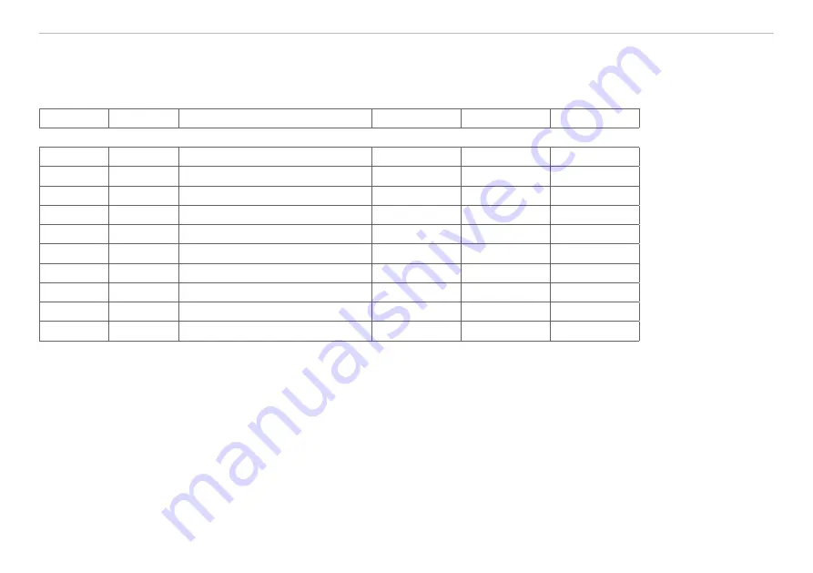
A 5.3.1.12 Object 1C33h: Synchronization Manager Input Parameters
1C33
RECORD
SM input parameter
ro
Subindices
0
VAR
Number of entries
9
Unsigned8
ro
1
VAR
Synchronization type
x
Unsigned16
ro
2
VAR
Cycle time
x
Unsigned32
ro
4
VAR
Supported synchronization types 0x4007
Unsigned16
ro
5
VAR
Minimum cycle time
100000
Unsigned32
ro
6
VAR
Calc and copy time
x
Unsigned32
ro
8
VAR
Get cycle time
x
Unsigned16
ro
9
VAR
Delay time
x
Unsigned32
ro
0C
VAR
Cycle time too small counter
x
Unsigned16
ro
20
VAR
Sync error
x
Bit
ro
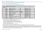
- Synchronization Type: currently specified synchronization, see
- Cycle Time: currently specified cycle time in ns
Free run: the cycle time derived from the measuring rate,
SM2, SM3: the cycle time derived from the measuring rate,
Sync0 synchronization, the Sync0 cycle time set by the master.
- Supported synchronization types:
Freerun, SM2 / SM3 and Sync0 synchronization
- Minimum cycle time: the minimum cycle time is derived from the maximum measuring rate and is 100 µs.
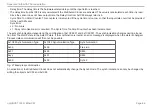
- Calc and Copy Time: The Calc and Copy time is the time after the input latch (input data are available in the slave) until the input
data is copied into the Sync-Manager-3 area (transfer of the data to Industrial Ethernet). The Calc and Copy Time from 0x1C33 is
only calculated if the Distributed Clocks are enabled. The value is recalculated each time it is read. Since the sensor does not have
output data, the Calc and copy time of 0x1C32 always returns 0.
Summary of Contents for ILD1900-10
Page 8: ...optoNCDT 1900 EtherCAT ...
Page 110: ...Page 110 Appendix EtherCAT Documentation optoNCDT 1900 EtherCAT ...
Page 111: ......

