AN1003
DS01003A-page 20
©
2005 Microchip Technology Inc.
APPENDIX A:
FREQUENTLY ASKED QUESTIONS
In this appendix, answers are provided to some of the frequently asked questions about the Mass Storage Device as
well as this implementation.
Q:
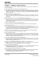
When I plug in the SD card, all of the LEDs turn on. What does this mean?
A:
This an indication that there was an error in the SD card initialization. Try removing the external power to the board
and USB cable, removing and reinserting the SD card, reconnecting the USB cable and external power (if applicable).
If this does not solve the problem, verify whether the SD card you are using has been tested with MSD (see Table 3
for the list of cards tested).
Q:
Which endpoints are used in the MSD application?
A:
Endpoint 0 is the mandatory endpoint that must be implemented in all USB devices for control transfers. This appli-
cation uses Endpoint 1 IN and OUT as Bulk transport endpoints for a bidirectional communication between the host
and the device.
Q:
What is the size of the
msd_buffer
and how does MSD handle large data transfers?
A:
The size of the
msd_buffer
is 512 bytes. Data is written to and read from the SD card in blocks which are
512 bytes for the SD card. Large data transfers imply multiple block read/write operations. However, the multi-read
and multi-write SD card commands are not implemented – instead, multiple single block read/write commands are
issued to achieve large transfers.
Q:
What is the size of the code in terms of single-word instructions?
A:
The size of Chapter 9 code is approximately 3K and Mass Storage Device code is approximately another 1K.
Q:
Why is LED D2 not blinking?
A:
After initial enumeration and reading the directory from the SD card, the host repeatedly sends the
TEST UNIT
READY
command to continue checking the status of the device. The D2 LED toggles when a
TEST UNIT READY
command returns a success. So if the D2 LED is not toggling, there was an error. Check whether the SD card was
properly inserted in the card reader interface before connecting the USB cable.
Q:
What is the communication protocol between the SD card and the PICDEM™ FS USB Demonstration Board?
A:
The SD card is operated in Single-Bit mode using the SPI bus protocol.
Q:
What is the data transfer speed?
A:
The maximum data transfer speed observed during MSD testing was 944 kbps. The data transfer speed of the
PICDEM™ FS USB bus is 12 Mbps. The system bottleneck is the SPI bus (with the SD card operated in Single-Bit
SPI Bus mode). We believe that reading 64 bytes from the endpoints into the
msd_buffer
and writing 512 bytes
into the SD card also slows the overall data transfer speed.
Q:
Is it possible to integrate the FAT file system into this implementation?
A:
Yes. The FAT file system is required if files need to be created on the SD card without using a PC (i.e., data logging
applications). However, it is possible to reuse the functions associated with the SCSI command interface and the
SD card communication interface in the firmware.
Q:
Why does it show “
Microchp
” in
Device Manager > Disk drives
? Is this a typographical error?
A:
Microchp
is an 8-byte Vendor ID sent from the device to the host in response to the
INQUIRY
command. Since
the Vendor ID field can be only 8 bytes,
Microchp
is a shortened version of Microchip.
Q:
Why doesn’t MSD work with Windows 98?
A:
The MSD demonstration uses the native Windows driver,
usbstor.sys
. The Windows 98 operating system does
not provide native support for
usbstor.sys
. Please refer to the Microsoft
®
web site for details:
http://www.microsoft.com/whdc/device/storage/usbfaq.mspx
Q:
Why does MSD implement the SCSI command set and not the RBC?
A:
Currently, Windows 2000 and Windows XP do not provide support to handle devices that implement Reduced Block
Commands (RBC, subclass 0x01) protocol. Please refer to the Microsoft web site for further details:
http://www.microsoft.com/whdc/device/storage/usbfaq.mspx
深圳市英锐恩科技有限公司
www.enroo-tech.com


