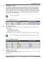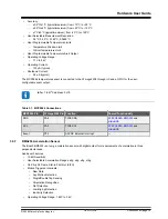
• Operating Current (Normal mode): 130 μA (typical)
• Shutdown Current (Deep Suspend mode): 1 μA (typical)
The BMA253 acceleration sensor is connected to the ATmega3208 through I
2
C and two GPIOs for the user
configurable interrupt outputs.
Info:
7-bit I
2
C address: 0x19
Table 3-8. BMA253 Connections
BMA253 Pin
ATmega3208 Pin Function
Shared Functionality
SDA
PA2
TWI0 SDA
,
and
SCL
PA3
TWI0 SCL
,
and
INT1
PC2
ASYNC External Interrupt
—
INT2
PC3
External Interrupt
—
3.5.8
LEDs
There are two user LEDs available on the AVR-BLE board that can be controlled by either GPIO or PWM. In addition,
there is one LED connected directly to the BLE module. The LEDs can be activated by driving their connected I/O
lines to GND.
Table 3-9. LED Connections
LED
ATmega3208 Pin
Function
Shared Functionality
Green Data LED
PF4
TCA0 WO4
Red Error LED
PF5
TCA0 WO5
—
Blue BLE LED
—
Connected to BLE module
3.5.9
Mechanical Switch
The AVR-BLE board has one mechanical switch. This is a generic user-configurable switch that will drive the
connected I/O line to ground (GND) when it is pressed. An external resistor pulls the signal high when the switch is
not pressed.
Table 3-10. Mechanical Switch Connection
Switch
ATmega3208 Pin
Function
Shared Functionality
SW0
PF3
User switch
Info:
The SW0 signal is pulled up by an external resistor.
Hardware User Guide
©
2020 Microchip Technology Inc.
User Guide
DS50002956A-page 20


