background image

Important: 

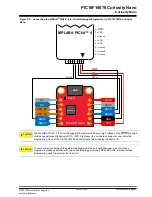
Once the pin-headers are in place, they are hard to remove by hand. Use a set of pliers and

carefully remove the pin-headers to avoid damage to the pin-headers and PCB.

4.2 

Peripherals

4.2.1 

LED

One yellow user LED is available on the PIC16F18076 Curiosity Nano board. It can be controlled by either GPIO or
PWM. Driving the connected I/O line to GND can also activate the LED.

Table 4-1. LED Connection

PIC16F18076 Pin

Function

Shared Functionality

RA1

Yellow LED0

Edge connector

4.2.2 

Mechanical Switch

The PIC16F18076 Curiosity Nano board has one mechanical switch - a generic user-configurable switch. Pressing it
will connect the I/O pin to ground (GND).

Tip: 

There is no externally connected pull-up resistor on the switch. The internal pull-up resistor on pin

RA0 must be enabled to use the switch.

Table 4-2. Mechanical Switch

PIC16F18076 Pin

Description

Shared Functionality

RA0

User switch (SW0)

Edge connector

On-board debugger

4.2.3 

Crystal

The PIC16F18076 Curiosity Nano board has a footprint for a 3.2 mm by 1.5 mm surface mount crystal with two
terminals.

The crystal footprint has a cut-strap (J211) next to it that can be used to measure the oscillator safety factor. This
is done by cutting the strap and adding a 0402 SMD resistor across the strap. More information about oscillator
allowance and safety factor can be found in the 

AN2648

 application note from Microchip.

The cut straps and solder points can be seen in 

Figure 4-4

.

Table 4-3. Crystal Connections

PIC16F18076 Pin

Function

Shared Functionality

RC0

SOSCO (Crystal output)

Edge connector

RC1

SOSCI (Crystal input)

Edge connector

Some hardware modifications are required to use RC0 and RC1 as GPIO.

WARNING

Before performing any hardware modifications, ensure that the board is disconnected from the USB or
external power.

 PIC16F18076 Curiosity Nano

Hardware Description

©

 2022 Microchip Technology Inc.

and its subsidiaries

 User Guide

DS50003399A-page 26

Summary of Contents for PIC16F18076

Page 1: ...device into a custom design The Curiosity Nano series of evaluation boards include an on board debugger No external tools are necessary to program and debug the PIC16F18076 MPLAB X IDE Software to di...

Page 2: ...3 1 Mass Storage Device Implementation 11 3 1 3 2 Configuration Words 12 3 1 3 3 Special Commands 12 3 1 4 Data Gateway Interface DGI 13 3 1 4 1 Debug GPIO 13 3 1 4 2 Timestamping 13 3 2 Curiosity Nan...

Page 3: ...n 3 28 6 Document Revision History 29 7 Appendix 30 7 1 Schematic 0 7 2 Assembly Drawing 33 7 3 Curiosity Nano Base for Click boards 35 7 4 Disconnecting the On Board Debugger 36 Microchip Information...

Page 4: ...the on board debugger 1 8 5 1V output voltage limited by USB input voltage 500 mA maximum output current limited by ambient temperature and output voltage 1 2 Board Overview The Microchip PIC16F18076...

Page 5: ...X IDE 4 Optional Use MPLAB Code Configurator to generate drivers and examples 5 Write Develop the application code 6 Connect a USB cable Standard A to Micro B or Micro AB between the PC and the debug...

Page 6: ...ensive solution for the project s software development on Windows macOS or Linux MPLAB XC8 supports all 8 bit PIC and AVR microcontrollers MCUs MPLAB Xpress Cloud Based IDE MPLAB Xpress Cloud Based ID...

Page 7: ...tion through terminal software A Data Gateway Interface DGI for code instrumentation with logic analyzer channels debug GPIO to visualize program flow The on board debugger controls a Power and Status...

Page 8: ...rminal Send Info The debugger s CDC TX pin is connected to a UART RX pin on the target for receiving characters from the host computer as shown in the figure above Similarly the debugger s CDC RX pin...

Page 9: ...ng behavior Debugger UART receiver is disabled and no further data will be transferred to the host computer Debugger UART transmitter will continue to send queued data ready for transfer but no new da...

Page 10: ...00 CMD SEND_115200 CMD SEND_460800 USB Level Framing Considerations Sending data from the host to the CDC can be done byte wise or in blocks chunked into 64 byte USB frames Each such frame will be que...

Page 11: ...due to the nature of FAT12 itself and optimizations made to fulfill its purpose for its embedded application The Curiosity Nano USB device is USB Chapter 9 compliant as a mass storage device but does...

Page 12: ...CDC UART at the specified baud rate Note that only the baud rates explicitly specified here are supported See CDC Override Mode Debugger firmware v1 21 or newer CMD RESET Resets the target device by e...

Page 13: ...bug GPIO in MPLAB Data Visualizer Figure 3 2 Monitoring Debug GPIO with MPLAB Data Visualizer Debug GPIO channels are timestamped so the resolution of DGI GPIO events is determined by the resolution o...

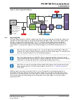
Page 14: ...out USB DEBUGGER PS LED NC ID CDC RX CDC TX DBG1 DBG2 VBUS VOFF DBG3 DBG0 GND VTG CURIOSITY NANO 3 3 Power Supply The USB port powers the board It contains two LDO regulators one to generate 3 3V for...

Page 15: ...hange to the target voltage is persistent even after a power toggle The resolution is less than 5 mV but may be limited to 10 mV by the adjustment program Info The voltage settings setup in MPLAB X ID...

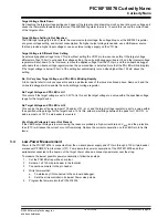
Page 16: ...e regulator back on 3 3 2 External Supply Instead of the on board target regulator an external voltage can power the PIC16F18076 Curiosity Nano When shorting the Voltage Off VOFF pin to the ground GND...

Page 17: ...ly 100 A will be drawn from any external power source to power the on board level shifters and voltage monitor circuitry when a USB cable is plugged into the DEBUG connector on the board When a USB ca...

Page 18: ...le the on board target voltage regulator No Target Voltage and PS LED is Lit 1 This occurs if the target voltage is set to 0 0V To fix this set the target voltage to a value within the specified volta...

Page 19: ...disconnected to prevent leakage as described in 7 4 Disconnecting the On Board Debugger 3 5 Programming External Microcontrollers The on board debugger on PIC16F18076 Curiosity Nano can be used to pr...

Page 20: ...p Studio allows any microcontroller and interface to be selected when the Hide unsupported devices setting is set to False also microcontrollers and interfaces not supported by the on board debugger 3...

Page 21: ...ata and clock signals used for programming and debugging DBG0 DBG1 and DBG2 Pull down resistors are required on the ICSP data and clock signals to debug PIC microcontrollers All other interfaces are f...

Page 22: ...nal Debuggers Even though there is an on board debugger external debuggers can be connected directly to the PIC16F18076 Curiosity Nano to program debug the PIC16F18076 When not actively used the on bo...

Page 23: ...liver high voltage on the MCLR pin High voltage can permanently damage R110 If R110 is broken the on board debugger cannot enter the programming mode of the PIC16F18076 and will typically fail at read...

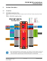
Page 24: ...OSCI GND GND VBUS VBUS VOFF VOFF DBG3 DBG3 RE3 MCLR DBG0 DBG0 RB7 ICSPDAT GND GND VTG VTG RD7 RD7 AND7 RD6 RD6 AND6 RD5 RD5 AND5 RD4 RD4 AND4 PWM 3 4 RD3 RD3 AND3 PWM 3 4 RD2 RD2 AND2 RD1 RD1 AND1 RD0...

Page 25: ...are firmly in place Figure 4 2 Attaching Pin Headers to the Curiostiy Nano Board Figure 4 3 Connecting to Curiosity Nano Base for Click boards Tip Start at one end of the pin header and gradually ins...

Page 26: ...n Shared Functionality RA0 User switch SW0 Edge connector On board debugger 4 2 3 Crystal The PIC16F18076 Curiosity Nano board has a footprint for a 3 2 mm by 1 5 mm surface mount crystal with two ter...

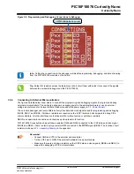
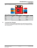
Page 27: ...debugging MPLAB Data Visualizer can be used as a front end for the CDC and debug GPIO 4 2 4 1 On Board Debugger Connections The table below shows the connections between the target and the debugger s...

Page 28: ...ing The first six digits of the serial number listed under kit information contain the product identifier and revision Tip If closed the Kit Window can be opened in MPLAB X IDE through the menu bar Wi...

Page 29: ...Revision History Doc Rev Date Comments A 09 2022 Initial document release PIC16F18076 Curiosity Nano Document Revision History 2022 Microchip Technology Inc and its subsidiaries User Guide DS50003399...

Page 30: ...7 Appendix PIC16F18076 Curiosity Nano Appendix 2022 Microchip Technology Inc and its subsidiaries User Guide DS50003399A page 30...

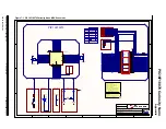
Page 31: ...ED 1 VBUS 48 CNANO48 pin edge connector J200 RB6_ICSPCLK RE2 RC2 RC3_SCL1 RB2_SCK2 RC4_SDA1 RC5 RC6_EUSART1_TX RD4_AND4_PWM RD0_AND0 RD1_AND1 RD2_AND2 RD3_AND3_PWM RB0_MOSI2 RB4_EUSART2_TX RC7_EUSART1...

Page 32: ...TX_CTRL CDC_RX_CTRL SWCLK REG_ADJUST DBG2_GPIO DBG3_CTRL DBG2_CTRL DBG3 1k R110 VBUS_ADC 1 2 3 DMN65D8LFB Q101 ID_SYS VOFF 1k R112 VCC_P3V3 VTG_ADC DAC MIC94163 VIN B2 VOUT A1 VIN A2 EN C2 GND C1 VOUT...

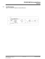
Page 33: ...Assembly Drawing Figure 7 3 PIC16F18076 Curiosity Nano Assembly Drawing Top PIC MCU PIC16F18076 Curiosity Nano Appendix 2022 Microchip Technology Inc and its subsidiaries User Guide DS50003399A page...

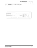
Page 34: ...Figure 7 4 PIC16F18076 Curiosity Nano Assembly Drawing Bottom 4 PIC16F18076 Curiosity Nano Appendix 2022 Microchip Technology Inc and its subsidiaries User Guide DS50003399A page 34...

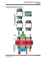
Page 35: ...riosity Nano Base for Click boards Figure 7 5 PIC16F18076 Curiosity Nano Pinout Mapping PIC16F18076 Curiosity Nano Appendix 2022 Microchip Technology Inc and its subsidiaries User Guide DS50003399A pa...

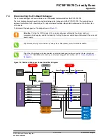
Page 36: ...strap will disconnect the on board power supply Tip Reconnect any cut connection by using solder Alternatively mount a 0 0402 resistor Tip When the debugger is disconnected an external debugger can be...

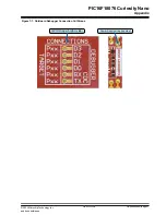
Page 37: ...On Board Debugger Connection Cut Straps GPIO straps bottom side Power Supply strap top side PIC16F18076 Curiosity Nano Appendix 2022 Microchip Technology Inc and its subsidiaries User Guide DS5000339...

Page 38: ...r representative or ESE for support Local sales offices are also available to help customers A listing of sales offices and locations is included in this document Technical support is available throug...

Page 39: ...nyAVR UNI O Vectron and XMEGA are registered trademarks of Microchip Technology Incorporated in the U S A and other countries AgileSwitch APT ClockWorks The Embedded Control Solutions Company EtherSyn...

Page 40: ...System For information regarding Microchip s Quality Management Systems please visit www microchip com quality PIC16F18076 Curiosity Nano 2022 Microchip Technology Inc and its subsidiaries User Guide...

Page 41: ...men Tel 86 592 2388138 China Zhuhai Tel 86 756 3210040 India Bangalore Tel 91 80 3090 4444 India New Delhi Tel 91 11 4160 8631 India Pune Tel 91 20 4121 0141 Japan Osaka Tel 81 6 6152 7160 Japan Tokyo...

Reviews: