background image

[1] 


DMX Click - User Manual 


Table of Contents 


DMX Click - User Manual ................................................................................................................................................... 1 

Introduction ........................................................................................................................................................................... 2 

The scope of this manual .................................................................................................................................................... 2 

What is DMX Click? .......................................................................................................................................................... 2 

Operating Modes ................................................................................................................................................................. 2 

UART interface ................................................................................................................................................................... 3 

Other considerations ........................................................................................................................................................... 3 

Configuring the Click board™ ............................................................................................................................................ 3 

MASTER/SLAVE selection ............................................................................................................................................... 3 

(MASTER) RUN mode ...................................................................................................................................................... 4 

(SLAVE) RUN mode .......................................................................................................................................................... 4 

(MASTER/SLAVE) CFG mode ......................................................................................................................................... 5 

DMX Start Code ................................................................................................................................................................. 5 

Configuration commands ..................................................................................................................................................... 5 

Commands structure ........................................................................................................................................................... 5 

MASTER mode commands ................................................................................................................................................ 6 

SLAVE mode commands.................................................................................................................................................... 7 

Appendix:............................................................................................................................................................................... 9 

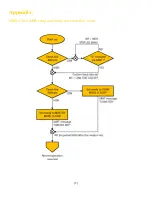
DMX Click ABR setup and mode selection flow chart ...................................................................................................... 9 


Summary of Contents for DMX Click

Page 1: ...ng Modes 2 UART interface 3 Other considerations 3 Configuring the Click board 3 MASTER SLAVE selection 3 MASTER RUN mode 4 SLAVE RUN mode 4 MASTER SLAVE CFG mode 5 DMX Start Code 5 Configuration comm...

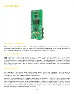
Page 2: ...e Click board also provides galvanic isolation between the DMX bus and the host application with no additional components required Operating Modes The Click board can be operated both as DMX MASTER an...

Page 3: ...ick board boots up it is possible to select the new UART baud rate and operating mode The end of the boot sequence is signalized by a short pulse on the INT pin and a response message over the TX pin...

Page 4: ...been received to fill the input buffer it will be swapped with the output buffer and an interrupt will signal that the input buffer is ready to receive a new data stream However the input buffer will...

Page 5: ...r or lf control characters should be used when sending a command The parser will treat them as regular values causing a misalignment of the input buffer Any buffer misalignment can be resolved with a...

Page 6: ...valid range is from od 001 to 512 Default 008 This is the length of the input buffer which will be mapped onto the output DMX frame NOTE The input buffer mapping boundaries defined by the SADR and BLE...

Page 7: ...iguration has been stored it will be always retrieved from the EEPROM The only way to revert to default values is to clear the stored configuration record This command will delete the stored configura...

Page 8: ...e received DMX frame length no error condition will be signaled In this case the SLAVE device will keep waiting for the particular channels that are out of range ITMR XXX XXX is the duration of the in...

Page 9: ...9 Appendix DMX Click ABR setup and mode selection flow chart...

Reviews: