background image

3.7  SEQUENCE DWELL

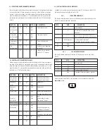
The sequence dwell interval defines how long the camera will stay active in the 
sequence. The factory default dwell time is 3 seconds, but this may be changed to any 
time between 1 and 99 seconds. 

SET SEQUENCE DWELL:
03

Use the 

POUND (#)

 key to scroll to Set 

Sequence Dwell. The current dwell time 
will be displayed.

Press the 

MENU

 button. Enter password 

if necessary.

SET SEQUENCE DWELL:
03

Using the key pad, enter the new dwell 
time. Press the 

STAR (*)

 key to set the 

time. Press 

MENU

 to exit the menu 

mode.

3.8  CONTROLLER ALARMS

The VLC485 responds to alarms from its alarm inputs. When an alarm occurs, a “go to 
preset” command will be sent to a predetermined pan/tilt. For example, alarm 3 may 
select preset 23 of camera 7 to be displayed. The preset number and pan/tilt number 
are preselected by using the alarm setup function.

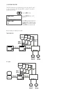
CAM 03              ALARM 1

When an alarm occurs, 

ALARM

 appears 

onscreen. The alarm message can only 
be cleared by pressing the 

ALARM


button.

Press the 

MENU

 button. Enter password 

if necessary.

ALARM 1             CAM 01

PRESET 03

To set up an alarm, enter the menu 
mode and scroll down to the “ALARM:” 
entry. Press the 

3.9  PASSCODE ENABLE/SET/CHANGE

You can protect your controller from unauthorized alterations by enabling the passcode 
function. This means that the menu cannot be accessed without the proper 4-digit. The 
VLC485 is factory set with PASSCODE disabled. To enable and set the passcode:

PASSCODE ENABLE:
NO

Use the 

POUND (#)

 key to scroll to 

Passcode Enable. 

Press the 

MENU

 button. 

PASSCODE ENABLE:
YES

Press 

STAR (*)

 to toggle between YES 

to enable and NO to disable. Press the 

POUND (#)

 key to enable the selection.

SET PASSCODE:
1234

On selecting YES, the default passcode 
will display. Change by entering a new 
4-digit code 

4.0  PC PORT

The VLC485 uses the PC port to communicate with the serial communications port of 
a PC or modem. The PC or other connected device uses a protocol to control either the 
VLC485 or other devices connected to the VLC485, such as the pan/tilt units. In addi-
tion, all controller activities, including joystick movements, are transmitted to the PC 
port. This enables the controller to become a “peripheral” to a PC and act as the man/
machine interface for a system. Following are the VLC485 protocols.

4.1  PC PORT COMMANDS

VLC485 RS232 COMMUNICATION PROTOCOL

(NOTE: This applies to software version 2.50 and later)

These messages are used to send and receive control messages from the PC.

4.2  GENERAL COMMAND MESSAGE FORMAT

Data is transmitted at 9600 baud, 1 start bit, 1 stop bit, 8 data bits (lsb first), no parity.

BYTE               DATA                           DESCRIPTION

1                    0x7e                         Start character "~"
2 - n               Data                         All data characters   
                                                      are 8-bit characters
n+1                0x0d                         "Carriage return" character
n+2                0x0a                         "Line feed" character

4.3  MOTION COMMAND MESSAGES

These commands control the basic motion of the pan/tilt platform and the lens  
movement of the camera system. The messages all comprise 5 bytes; the Data is 
contained in bytes 2 and 3 as described in the following table. Messages that are 
transmitted from the controller are indicated by a “T” in the direction column, D;  
messages that are received and processed by the controller are indicated by a “R” in 
the direction column. 

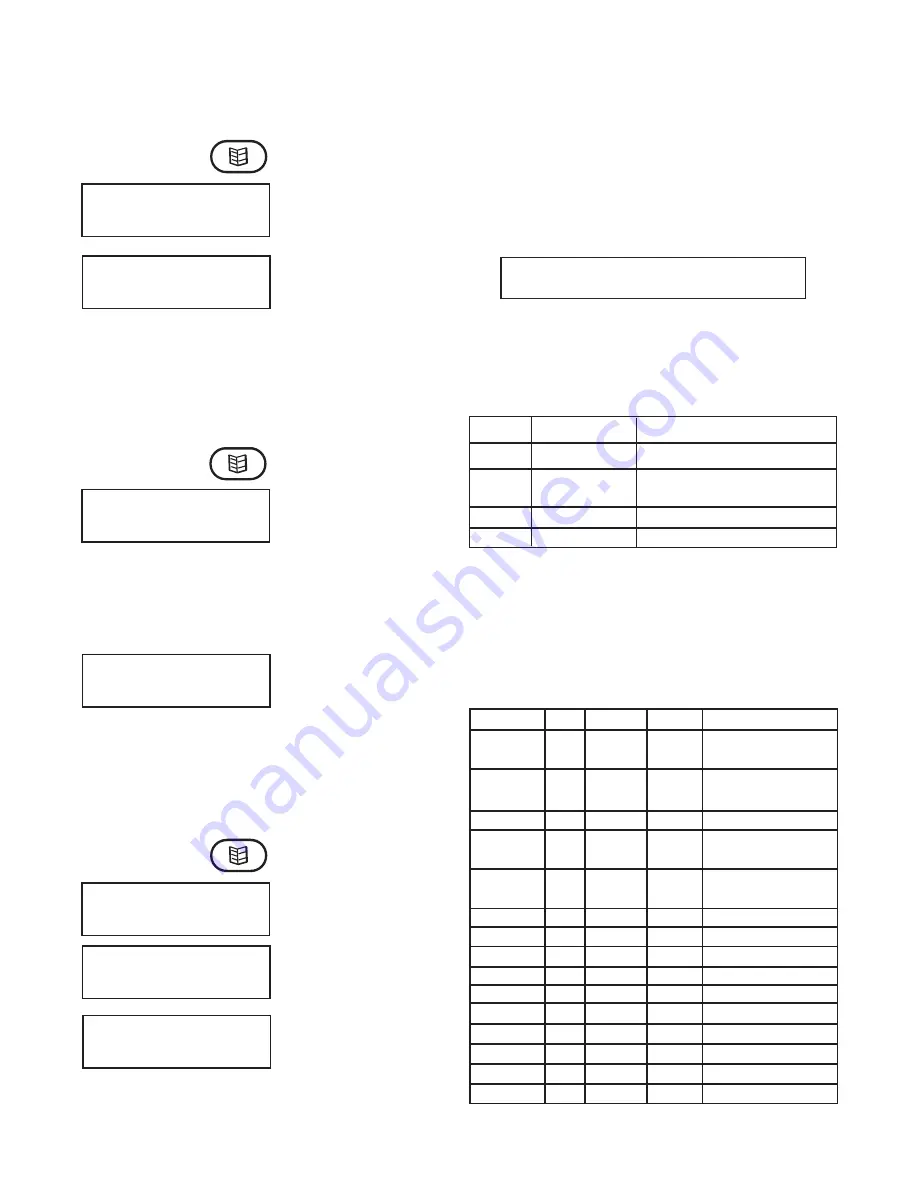
FUNCTION             D           BYTE #2       BYTE #3        DESCRIPTION

Pan left at speed 
"x" 
Pan right at 
speed "x"
Pan stop
Tilt up at speed 
"x"
Tilt down at 
speed "x"
Tilt stop
Zoom in
Zoom out
Zoom stop
Focus near
Focus far
Focus stop
Iris open
Iris close
Iris stop

T/R

T/R

T/R
T/R

T/R

T/R
T/R
T/R
T/R
T/R
T/R
T/R
T/R
T/R
T/R

"1"

"r"

"P"
"u"

"d"

"T"
"Z"
"Z"
"Z"
"F"
"F"
"F"
"I"
"I"
"I"

"0" - "?"

"0" - "?"

"S"
"0" - "?"

"0" - "?"

"S"
"I"
"O"
"S"
"N"
"F"
"S"
"O"
"C"
"S"

Pan left at speed index 0 - 15
Pan right at speed index 
0 - 15

Tilt up at speed  index 0 - 15
Tilt down at speed  index 
0 - 15

Zoom in (Telephoto)
Zoom out (Wide angle)

Focus on nearby objects
Focus on distant object

STAR


(*)

 button to scroll to the desired alarm number. The display will show the 

camera number and preset associated with the alarm. Use the keypad to enter or 
change the camera number and press the 

CAMERA

 button. Use the keypad to enter 

or change the preset number and press the 

PRESET

 button. Press STAR (*) to select 

another alarm, or exit the menu by pressing the 

MENU

 button.

on the key pad. Press 

STAR (*)

POUND (#)

 or the 

MENU

 button to enable the 

passcode and automatically exit the menu mode.

Summary of Contents for VLC485

Page 1: ...5 RS485 controller 2 RS232 ports 1 RS485 port joystick control Desk top model 24Vac input power VLC485E 230Vac PAL version Before attempting to connect or operate this product please read these instructions completely 81 IN5240 01 11 2012 2011 Moog Videolarm Inc All Rights Reserved VLC485 and VLC485E ...

Page 2: ...n be damaged if improperly handled or dropped If an item appears to have been damaged in shipment replace it properly in its carton and notify the shipper Be sure to save 1 The shipping carton and packaging material They are the safest material in which to make future shipments of the equipment 2 These Installation and Operating Instructions If technical support or service is needed contact us at ...

Page 3: ...spect to any Product requiring service during the warranty period which is subjected to any of the following abuse improper use negligence accident lightning damage or other acts of God i e hurricanes earthquakes modification failure of the end user to follow the directions outlined in the product instructions failure of the end user to follow the maintenance procedures recommended by the Internat...

Page 4: ...r the system As such the VLC485 can control pan tilt units interface to multiplexers and communicate with a personal computer for computer controlled operation The LCD is used to display current status as well as to provide a menu system for setting operational parameters The VLC485 is designed for desktop operation all connectors are located in the rear of the unit so that all cables can be route...

Page 5: ...INPUT OUTPUT CONNECTORS 1 2 3 4 5 6 7 8 9 0 1 2 3 F Alarm Camera Monitor for future use Presets Menu Sequence Auxiliary for future use Function for future use Auto Tour Zoom Out Zoom In Focus Far Focus Near Iris Close Iris Open 5VDC R R A B A B C 8 7 6 5 4 3 2 1 N N O C OUT IN Power Input RS 485 Control Alarm Inputs Alarm Outputs PC Port MUX Port T T C ...

Page 6: ... to operate the zoom function of a selected camera NOTE Whenever the camera zoom is changed the controller places the camera into auto focus and auto iris mode if these modes are available If you want to focus a camera manually press the FOCUS FAR FOCUS NEAR keys The IRIS CLOSED IRIS OPEN keys will allow you to change the iris setting of a camera NOTE Some cameras provide continuous iris function ...

Page 7: ...e camera position which means that you can build a system using multiple dome types TO CHANGE CAMERA PROTOCOL CAM 04 DOME TYPE VIDEOLARM Select a camera The current pan tilt type will display To select a different type press the STAR key until the desired type is displayed Press the POUND key to enter the selection Press MENU to exit the menu mode Press the MENU button Enter password if necessary ...

Page 8: ...you press it the next camera will be displayed When a blank appears that will be the end of the sequence 1 2 3 3 6 1 TO REVIEW A SEQUENCE A blank space will appear after the last camera of the current sequence 3 6 2 TO ADD A CAMERA TO A SEQUENCE A sequence may contain up to 16 camera entries If you have not filled a sequence and would like to add cameras to it do the following To add a camera to t...

Page 9: ...ion all controller activities including joystick movements are transmitted to the PC port This enables the controller to become a peripheral to a PC and act as the man machine interface for a system Following are the VLC485 protocols 4 1 PC PORT COMMANDS VLC485 RS232 COMMUNICATION PROTOCOL NOTE This applies to software version 2 50 and later These messages are used to send and receive control mess...

Page 10: ... DESCRIPTION Camera select Monitor select Sequence status Sequence status Alarm active Alarm kill Aux function aux01 aux99 Information key Menu active Menu inactive T R T R T T T T R T T T T C M S S A A X B M M 0x01 0x63 0x01 0x63 0x00 0x01 0x01 0x0a K 0x01 0x6c B A I Current camera number Current monitor number Sequence off Sequence on Active alarm number Alarm has been detected on alarm input Ac...

Page 11: ...485 can be used in as a stand alone unit or as part of a system As part of a system the unit may be used with another VLC485 or with a PC The function is enabled through the menu MASTER UNIT NO Use the POUND key to scroll to Master Unit Press the MENU button MASTER UNIT YES Press STAR to toggle between YES to enable and NO to disable Press the POUND key to enable the selection Press MENU to exit t...

Page 12: ...Housings Poles Power Supplies and Accessories and 5 Years on camera systems SView QView Warriors and InfraRed Illuminators Register Your ProductsOnline Take a few moments and validate your purchase via the Online Product Registration Form at www videolarm com productregistration jsp Register your recent Moog Videolarm purchases and benefit from the following Simple and Trouble Free RMA process Add...

Reviews: