Moog ACV with CANopen bus interface
6 Signal routing and scaling
Encoder input
B99224-DV018-D-211, Rev. A, October 2018
95
6.6 Encoder input
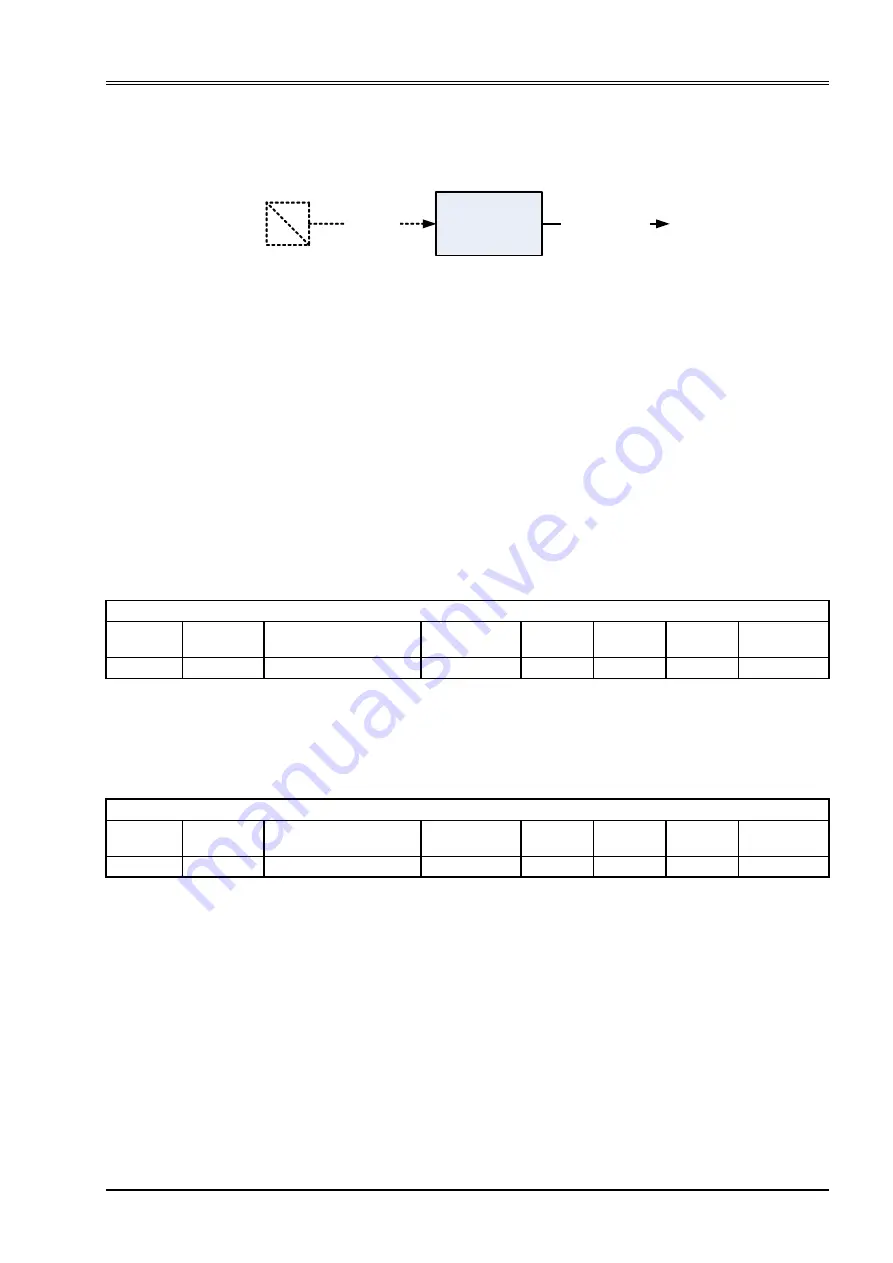
The servo valve has one encoder input.
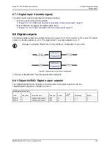
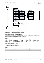
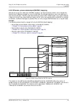
Figure 37: Encoder input
See also document CA63420-001 "User Manual Electrical Interfaces"
The encoder input can be used to measure the position of a hydraulic axis. This position will be used by the
axis position controller in order to close the control loop. The parameter <Type> (0x6202) will select the type
of the encoder (SSI binary, SSI gray or incremental)
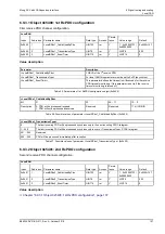
It is possible to map the output of the encoder <EncoderValue> (0x5613) to more than one
<TransducerPort> (0x4032) . In this case the first of this transducer ports is used to initialize the encoder
hardware.
Chapter "6.3.9.3 Object 0x6202: Type", page 76
Chapter "6.3.9.6 Object 0x4032: Transducer port", page 77
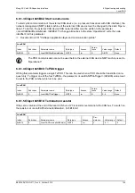
6.6.1 Object 0x5613: Encoder value
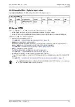
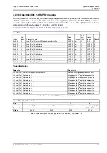
This raw value is the output from the encoder. It can be mapped to a transducer interface to be scaled to the
needs of the application.
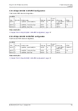
6.6.2 Object 0x5621: Encoder set value
This value is the input of the encoder. With this parameter the encoder value can be set (for example, with
z-pulse, during reference mode, setting an offset).
s
u
SSI / incremental
encoder
Connector
X2
<EncoderValue>
(0x5613)
Drive_ActualValueConditioning
Index
Sub-index
Parameter name
Data type
Access
Per-
sistence
Value
range
Default
0x5613
0
EncoderValue
UINT32
rw
N
UINT32
None
Drive_ActualValueConditioning
Index
Sub-index
Parameter name
Data type
Access
Per-
sistence
Value
range
Default
0x5621
0
EncoderSetValue
INT32
rw
Y
INT32
0


