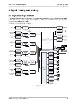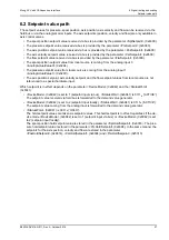
Moog ACV with CANopen bus interface
6 Signal routing and scaling
Setpoint value path
B99224-DV018-D-211, Rev. A, October 2018
70
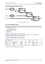
6.2.6.4.4 Object 0x5526: Maximum interface
This parameter together with the parameter <VelMaximumReference> (0x5524) results in the second point of
the linear scaling function.
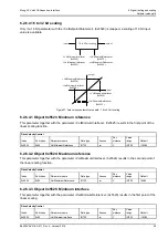
6.2.7 Flow setpoint value path
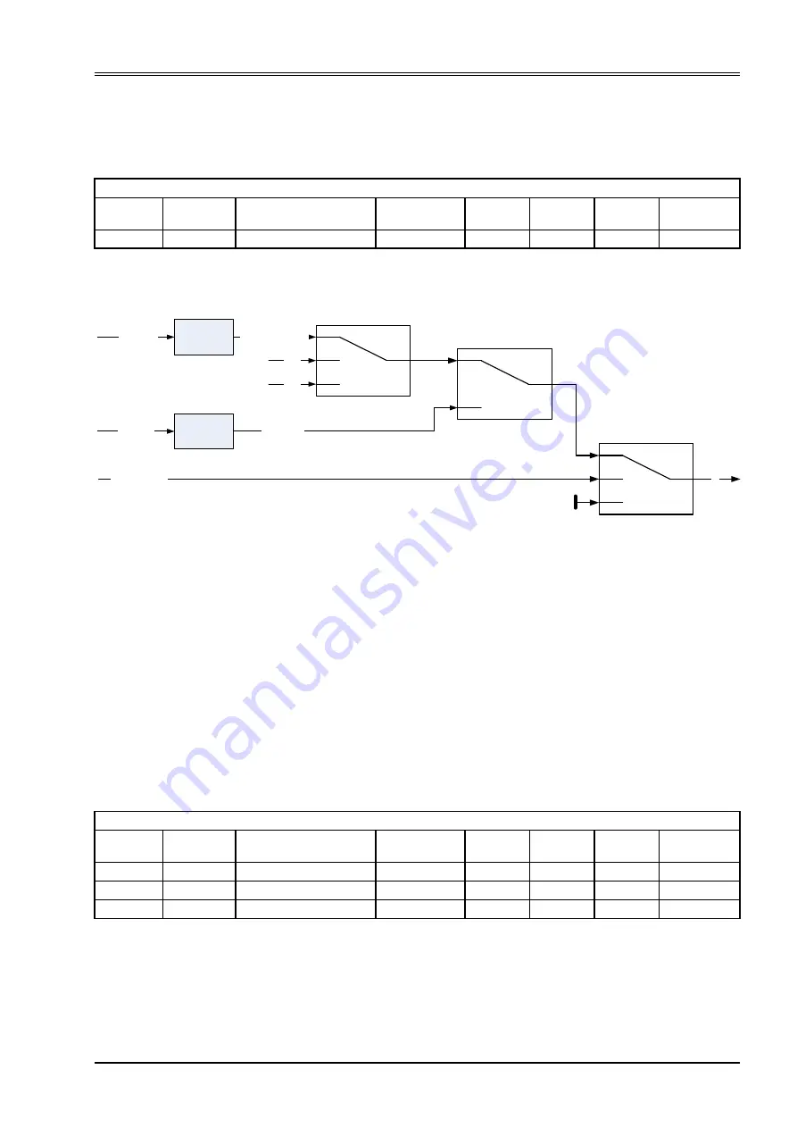
Figure 28: Flow setpoint value path
6.2.7.1 Object 0x5300: Setpoint
This parameter contains the flow setpoint value which is received from the field bus. Depending on the
<DeviceMode> (0x6042), this parameter is in effect for the following control modes stored in the parameter
<ControlMode> (0x6043):
Chapter "7.1.1 Object 0x6043: Control mode", page 128
The setpoint value takes only effect in case the <StatusWord> (0x6041) is 1111
b
('ACTIVE') and the
<DeviceMode> (0x6042) is set to 1 (setpoint input via bus).
Chapter "5.2.3 Object 0x6041: Status word", page 52
Chapter "6.2.1 Object 0x6042: Device mode", page 58
Chapter "2.4.3 Units and prefix parameter", page 12
DriveVelocityControl
Index
Sub-index
Parameter name
Data type
Access
Per-
sistence
Value
range
Default
0x5526
0x00
VelMaximumInterface
INT32
rw
Y
INT32
16384
<AnaInpActualValue0>
(0x3204)
<FlwSetpoint>
(0x5300)
#F
lowSetpoin
t#
<StatusWord>
(0x6041)
’ACTIVE’
’HOLD’ or
’FAULT HOLD’
’INIT’ or ’DISABLED’ or
’FAULT DISABLED’
<FlwSetpointParameter>
(0x5202)
0x32010010
0x...
0x...
<...>
(0x...)
<...>
(0x...)
Object 0x1600:
RxPDO mapping
flow setpoint
value from
field bus
Analog input 0
<FlwHoldSetPoint>
(0x5314)
1 (Setpoint input via the bus)
2 (Setpoint input locally)
<DeviceMode>
(0x6042)
flow setpoint
value from
analog signal
13 flow control
14 p/flow control
DriveFlowControl
Index
Sub-index
Parameter name
Data type
Access
Per-
sistence
Value
range
Default
0x5300
1
FlwSetpoint
INT16
rw
N
INT16
None
0x5300
2
Unit
UINT8
ro
-
UINT8
0
0x5300
3
Prefix
INT8
ro
-
INT8
0

