Chapter 15. Debug Features
15-21
JTAG/Testing Support
15.6 JTAG/Testing Support
The MPC8240 provides a joint test action group (JTAG) interface to facilitate
boundary-scan testing. The JTAG interface complies to the IEEE 1149.1 boundary-scan
specification. For additional information about JTAG operations, refer to the IEEE 1149.1
specification.
The JTAG interface consists of a set of five signals, three JTAG registers, and a test access
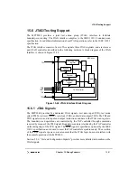
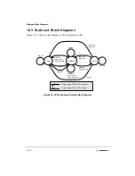
port (TAP) controller, described in the following sections. A block diagram of the JTAG
interface is shown in Figure 15-24.
Figure 15-24. JTAG Interface Block Diagram
15.6.1 JTAG Signals
The MPC8240 provides five dedicated JTAG signals—test data input (TDI), test mode
select (TMS), test reset (TRST), test clock (TCK), and test data output (TDO). The TDI and
TDO signals are used to input and output instructions and data to the JTAG scan registers.
The boundary-scan operations are controlled by the TAP controller through commands
received by means of the TMS signal. Boundary-scan data is latched by the TAP controller
on the rising edge of the TCK signal. The TRST signal is specified as optional by the IEEE
1149.1 specification and is used to reset the TAP controller asynchronously. The assertion
of the TRST signal at power-on reset ensures that the JTAG logic does not interfere with
the normal operation of the MPC8240.
Section 2.2.6, “Test and Configuration Signals,” provides more detailed information on the
JTAG signals.
Boundary-Scan
register
Instruction
register
Decoder
MUX
MUX
TAP controller
TDI
TMS
TRST
TCK
TDO
Bypass
register
MPC8240
Summary of Contents for MPC8240
Page 1: ...MPC8240UM D Rev 1 1 2001 MPC8240 Integrated Processor User s Manual ...
Page 38: ...xviii MPC8240 Integrated Processor User s Manual TABLES Table Number Title Page Number ...
Page 48: ...xlviii MPC8240 Integrated Processor User s Manual Acronyms and Abbreviations ...
Page 312: ...6 94 MPC8240 Integrated Processor User s Manual ROM Flash Interface Operation ...
Page 348: ...7 36 MPC8240 Integrated Processor User s Manual PCI Host and Agent Modes ...
Page 372: ...8 24 MPC8240 Integrated Processor User s Manual DMA Register Descriptions ...
Page 394: ...9 22 MPC8240 Integrated Processor User s Manual I2O Interface ...
Page 412: ...10 18 MPC8240 Integrated Processor User s Manual Programming Guidelines ...
Page 454: ...12 14 MPC8240 Integrated Processor User s Manual Internal Arbitration ...
Page 466: ...13 12 MPC8240 Integrated Processor User s Manual Exception Latencies ...
Page 516: ...16 14 Watchpoint Trigger Applications ...
Page 538: ...B 16 MPC8240 Integrated Processor User s Manual Setting the Endian Mode of Operation ...
Page 546: ...C 8 MPC8240 Integrated Processor User s Manual ...
Page 640: ...INDEX Index 16 MPC8240 Integrated Processor User s Manual ...

