Programming
Chapter 5
SCXI-1100 User Manual
5-12
© National Instruments Corporation
3. Perform the steps outlined in the 3. Programming the Slot 0 Hardscan Circuitry section
earlier in this chapter, where step 3, Write the Slot 0 scan list to the FIFO, consists of the
following:
Write
00000000 00000110
to the FIFO Register. This corresponds to Slot 1 for
seven samples.
4. Perform the procedure given in the 4. Acquisition Enable, Triggering, and Servicing section
earlier in this chapter.
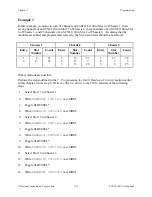
Example 2
An SCXI-1000 chassis has SCXI-1100 modules in Slots 1, 2, 3, and 4. The SCXI-1100 in Slot 4
is cabled to the data acquisition board. You want to scan channels 17 through 25 on the
SCXI-1100 in Slot 1 at a gain of 1, channels 0 through 29 on the SCXI-1100 in Slot 4 at a gain of
50, and channels 28 through 7 on the SCXI-1100 in Slot 3 at a gain of 2,000.
The programming steps are as follows:
1. Program your data acquisition board as described in the 1. Data Acquisition Board Setup
Programming section earlier in this chapter.
2. Performing the procedure given in the Register Writes section earlier in this chapter, write
00000000 00000000 00000000
to the Configuration Register of the SCXI-1100 in Slot
2. This step resets the module, including the clearing of the AB0EN bit (bit 0). Notice that a
complete reset of this module is not necessary, but is used for simplicity.
3. Performing the procedure given in the Register Writes section earlier in this chapter, write
XXX01001 10X00000 00000111
to the Configuration Register of the SCXI-1100 in
Slot 4.
4. Performing the procedure given in the Register Writes section earlier in this chapter, write
XXX00000 01X10001 00000111
to the Configuration Register of the SCXI-1100 in
Slot 1.
5. Performing the procedure given in the Register Writes section earlier in this chapter, write
XXX10010 01X11100 00000111
to the Configuration Register of the SCXI-1100 in
Slot 3. Notice that after Channel 31, the SCXI-1100 will wrap around to Channel 0.
6. Perform the steps given in the 3. Programming the Slot 0 Hardscan Circuitry section earlier
in this chapter, where step 3, Write the Slot 0 scan list to the FIFO, consists of:
a. Write
00000000 00001000
to the FIFO Register. This corresponds to Slot 1 for nine
samples.
b. Write
00000001 10011101
to the FIFO Register. This corresponds to Slot 4 for 30
samples.
c. Write
00000001 00001011
to the FIFO Register. This corresponds to Slot 3 for 12
samples.
Make sure to toggle SLOT0SEL* or reselect the FIFO Register from scratch between steps
6a, 6b, and 6c.
7. Perform the procedure given in the 4. Acquisition Enable, Triggering, and Servicing section
earlier in this chapter.

