8-28
|
ni.com
Chapter 8
Developing Applications for the High-Speed Serial Device
N Point Eye Scan
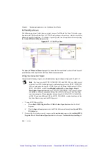
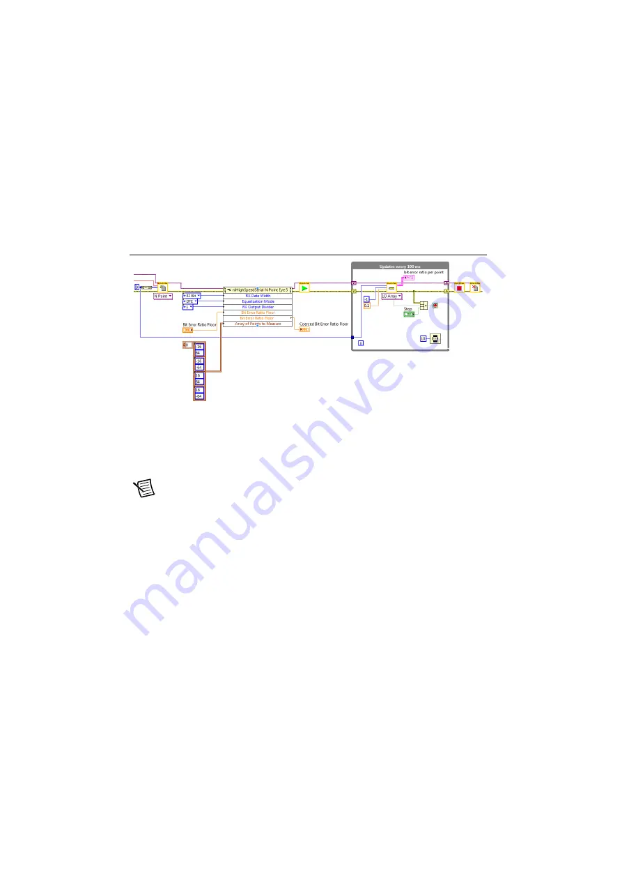
The following portion of code shows a typical use case for N Point Eye Scan. This code scans
4 points with a Bit Error Ratio floor of 2.33E-10 and produces a 4-point eye, which is useful for
measuring pass/fail conditions. To obtain a 6-point eye, add two extra points to the array using
the
Array of Points to Measure
property.
Figure 8-11.
N Point Eye Scan
The
Array of Points to Measure
property contains the horizontal and vertical offsets for each
point that you wish to perform a Bit Error Ratio measurement on.
Wiring the Instruction Targets
Complete the following steps to wire the instruction targets shown in Figures 8-10 and 8-11.
Note
Eye Scan uses the GTX2_CHANNEL UID with UID 1206 as a child context
of the top-level UID. In the high-speed serial sample projects, the GTX2_CHANNEL
UID is nested under the top-level UID. If you use a different child context UID for
GTX2_CHANNEL, modify the
niHighSpeedSerial Eye Scan Single Point v1
Host.lvclass:Open Session.vi
to use your GTX2_CHANNEL's UID. Since Eye Scan
is installed as a shared component, doing this will affect all uses of Eye Scan from
your host computer. NI recommends that you keep the UID of GTX2_CHANNEL
at 1206. If you use a different UID for GTX2_CHANNEL, create a local copy of the
Eye Scan libraries in your LabVIEW project.
1.
Create a FIFO Register Bus.
a.
Place
niInstr FIFO Register Bus v1 Host.lvclass:Open Session.vi
on the block
diagram.
b.
Wire the
fpga ref
input parameter to the FPGA Reference obtained from
Open FPGA
VI Reference
.
2.
Retrieve the list of subsystems by connecting the
session out
parameter from
niInstr FIFO
Register Bus v1 Host.lvclass:Open Session.vi
to the input of
niInstr Subsystem Map v1
Artisan Technology Group - Quality Instrumentation ... Guaranteed | (888) 88-SOURCE | www.artisantg.com


