ISD94100 Series Technical Reference Manual
Sep 9, 2019
Page
342
of 928
Rev1.09
IS
D
9
410
0
S
ER
IE
S
T
E
C
HN
ICA
L
RE
F
E
RE
NCE
M
AN
U
AL
APB
TIMERx_PWM
TMR0
PCLK0/1
TMR1
TMR2
TMR3
TMx, x=0~3
(PWMx_CH0)
TMx_EXT, x=0~3
(PWMx_CH1)
NVIC
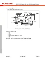
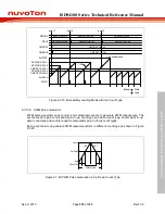
Figure 6.7-3 PWM Generator Overview Block Diagram
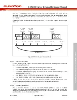
In PWM mode, the timer clock source, i.e. now the PWM system clock, TMR0_CLK and TMR1_CLK
clock sources are fixed to be from PCLK0; TMR2_CLK and TMR3_CLK clock sources are fixed to be
from PCLK1,
shown in Figure 6.7-4 .
Further, the PWM counter (TIMERx_PWMCLK) clock source can be selected from TMRx_CLK (PWM
system clock ) or Timer interrupt events (TMRx_INT) as shown in Figure 6.7-5.
TMR0_CLK
TMR1_CLK
PCLK0
TMR0CKEN (CLK_APBCLK0[2])
TMR1CKEN (CLK_APBCLK0[3])
PCLK1
TMR2_CLK
TMR3_CLK
TMR2CKEN (CLK_APBCLK0[4])
TMR3CKEN (CLK_APBCLK0[5])
Figure 6.7-4 PWM System Clock Source Control


