ISD94100 Series Technical Reference Manual
Sep 9, 2019
Page
769
of 928
Rev1.09
IS
D
9
410
0
S
ER
IE
S
T
E
C
HN
ICA
L
RE
F
E
RE
NCE
M
AN
U
AL
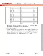
Table 6.16.5-2 EADC Power Saving Mode
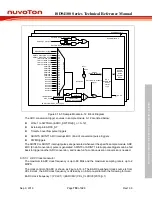
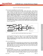
When EADC is activated by setting ADCEN(EADC_CTL[0]) to 1, the startup sequence will execute
automatically. After start up sequence finished, PWUPRDY (EADC_PWRM[0]) will be set to 1 by
HW which means ready to convert. ADCEN (EADC_CTL[0]) must be kept at 1 until PWUPRDY
(EADC_PWRM[0]) is set to 1 during the startup sequence. Changing ADCEN (EADC_CTL[0])
arbitrarily at start up sequence will cause EADC function failure.
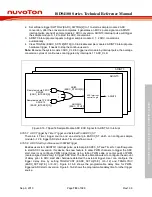
The conversion results of ADC will be more accurate with calibration. User may set PWUCALEN
(EADC_PWRM[1]) as 1 to carry out calibration at start up. An example about start up with calibration
is shown as Figure 6.16-15.
LDO Start-up
Transition
Ready
ADC Internal LDO Start-up Time
LDOSUT(EADC_PWRM[19:8])
Power Down
PWUPRDY
PWUCALEN
ADC clock
ADCEN
Calibration
ADC status
Figure 6.16-15 ADC start up sequence with calibration
6.16.5.16 Minimum ADC Sampling Time
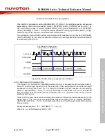
The Figure 6.16-16 shows the (simplified) equivalent circuit of the sample and hold input network,
where C
S
is the storage capacitor, R
S
is the resistance of the sampling switch and R
I
is the output
impedance of the signal source (V
I
). For minimum conversion cycles, duration of the sampling
phase is, approximately, 1.5/f
ADC_CLK
. C
S
must be charged in that phase, and it must be ensured
that the voltage at its terminals becomes sufficiently near V
I
. To guarantee this, R
I
may not take
arbitrarily large values.
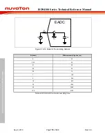
Table 6.16.5-3 shows the minimum sampling time relative to different output impedance (R
I
) of the
signal source. The user must set appropriate extend sampling time by register EXTSMPT
(EADC_SCTLx[31:24], x = 0~12). The following describes how to set the appropriate ADC sampling
time extension.
Minimum sampling time < (1.5 + EXTSMPT) * (1 / f
ADC_CLK
)
Where f
ADC_CLK
is the frequency of ADC_CLK.

