ISD94100 Series Technical Reference Manual
Sep 9, 2019
Page
898
of 928
Rev1.09
IS
D
9
410
0
S
ER
IE
S
T
E
C
HN
ICA
L
RE
F
E
RE
NCE
M
AN
U
AL
PD.0
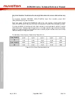
MFP5
DPWM_LP
PA.5
MFP3
PC.13
MFP3
PD.1
MFP5
DPWM_RN
PA.10
MFP3
PC.10
MFP3
PD.5
MFP5
DPWM_RP
PA.11
MFP3
PC.11
MFP3
PD.6
MFP5
DPWM_SN
PA.13
MFP3
PC.14
MFP3
PD.8
MFP5
DPWM_SP
PA.14
MFP3
PC.15
MFP3
PD.9
MFP5
6.21.5 Functional Description
The DPWM block receives audio data by writing PCM audio to the FIFO. FIFO is accessed through
PDMA for ease of streaming. The audio stream is sampled by a zero-order hold and fed to an
upsmaple filter. The signal is then modulated and sent to the driver stage through a non-overlap
circuit. Master clock rate of the Delta-Sigma modulator is controlled by DPWM_CLK. This clock is
generated by the internal system clock.
6.21.5.1 DPWM Clock Generation
The DPWM module has two clock sources selected by register
DPWMSEL
(CLK_CLKSEL2[13:12]). The DPWM clock control diagram is shown in Figure 6.21-2. Note that the
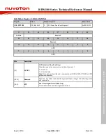
frequency of DPWM_CLK must be 512 fs (Sample rate) or 500 fs according to the value of register
CLKSET (DPWM_CTL[31]).
DPWM_CLK
PLL FOUT
PCLK0
01
10
DPWMSEL (CLK_CLKSEL2[13:12])
DPWMCKEN (CLK_APBCLK1[6])
1/( 1)
Note:
Before clock switching, both the pre-selected and newly
selected clock sources must be turned on and stable.
HXT
00
HIRC
11
CLKDIV = DPWM_ZOHDIV[15:8]

