background image


Web Site:

 www.parallax.com 

Forums:

 forums.parallax.com 

Sales:

 sales@parallax.com 

Technical:

 support@parallax.com 


Office: 

(916) 624-8333 

Fax: 

(916) 624-8003 

Sales: 

(888) 512-1024 

Tech Support: 

(888) 997-8267


Copyright © Parallax Inc.


Mouse Sensor Kit (#28560) 

v1.0  6/1/2010  Page 1 of 18 

Mouse Sensor Kit (#28560) 

The  Parallax  Mouse  Sensor  is  a  module  in  kit  form  which,  when  assembled,  provides  the  tracking 
functions of an optical mouse. The two-wire serial interface is directly compatible with the Parallax BASIC 
Stamp

®

 2 family, the Parallax Propeller, and other microcontrollers. 

Features 


Compact module, including illumination, optics, and custom laser-cut base 


“Close-to-the-metal” register-based serial interface for maximum flexibility 


Holes for mounting to other equipment 


Compatible with any BS2-family BASIC Stamp

®

, the SX, and the Parallax Propeller 


Accommodation for single or dual three-wire (servo-type) interface cables 

Key Specifications 


Power requirements: 5 VDC at 35 mA 


Communication: Two-wire serial (clock and data) 


Logic compatible with 3.3V (using external resistor) and 5V microcontrollers 


Dimensions: 1.80” (45.7mm) L x 1.00” (25.4 mm) W x 0.65” (16.5 mm) H 

Application Ideas 


Measuring X and Y displacement on a flat surface 


Detecting vibration in two dimensions over a flat surface 

What Comes with the Kit 

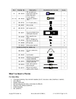
Part 

Parallax No. 

Description 

Illustration (not to scale) 

Quan. 


300-28560 

Printed circuit board 


U1 

604-28560 

MCS-12086 mouse 
sensor chip 

1

2

0

8

6

 0

9

3

4

1


LED1 

350-00031 

Red T1¾ LED (lens 
may be red or clear) 


350-00032 

Right-angle LED holder 


721-28560 

Clear plastic lens/light 
guide 


D1 

501-00008 

1N5817 Schottky diode 


R1, R2 

150-01021 

1K 1/8 W resistor 
(brown, black, red) 


R3 

150-01022 

100

 1/8 W resistor 

(brown, black, brown) 


Summary of Contents for 28560

Page 1: ...patible with any BS2 family BASIC Stamp the SX and the Parallax Propeller Accommodation for single or dual three wire servo type interface cables Key Specifications Power requirements 5 VDC at 35 mA C...

Page 2: ...2 x Phillips pan head machine screws 4 711 00004 2 hex nuts 4 713 00018 White nylon spacers 4 Additional Parts for Interfacing 805 00002 14 servo extension cable 2 451 00303 3 pin header 2 500 00008 2...

Page 3: ...o the right and of C1 positive lead the longer one goes to the top Take your time and make sure that all parts are firmly seated against the board For J1 and J2 solder the diagonal corner pins first a...

Page 4: ...st if dropped Work in a location such that if you do drop something you will be able to find it again Working on top of a folded towel can help to avoid parts bouncing and getting lost 1 There are two...

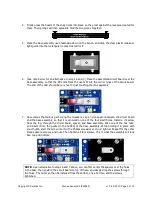
Page 5: ...w comes the tedious part Using the tweezers slip a nylon spacer between the circuit board and the base assembly so that it is centered on one of the four small holes Install a 2 screw from the top thr...

Page 6: ...es 3 Press the chip into the board as far as you can It will probably touch the lens assembly which is good 4 Making sure the chip is level with the board solder one of its corner pins from the top si...

Page 7: ...further with a BASIC Stamp wire it as shown above Then upload the program mouse_monitor bs2 shown at the end of this document and downloadable from the Mouse Sensor product page search 28560 at www pa...

Page 8: ...ile the Mouse Sensor is very good at tracking relative motion it does accumulate small errors when keeping track of absolute position To demonstrate this make a small mark at the sensor s current loca...

Page 9: ...with the kit Using this circuit entails a change in the program since the clock is now inverted from what it was This is easily accomplished by commenting out the line that says DEFINE NEG_CLK DEFINE...

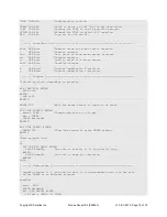
Page 10: ...hat it can recognize from one snapshot to the next Communication with the chip takes place by reading and writing its internal registers The most important of these are listed below Address Type Descr...

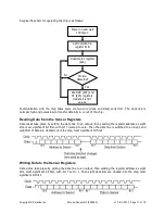
Page 11: ...er address as eight bits most significant bit first with bit 7 cleared to zero Then the data line is switched to an input and eight bits of data are clocked out of the chip most significant bit first...

Page 12: ...Clk B Serial Clock Input Option B Options Header Pin Shunt Configurations Pin Pair Configuration B C Connect Clk B to sensor chip s clock input A C Connect Clk A to sensor chip s clock input A V Conn...

Page 13: ...e Sensor Kit 28560 v1 0 6 1 2010 Page 13 of 18 Mouse Sensor Dimensions Mouse Sensor Schematic 1N5817 D LED1 V C B A J1 100R R3 D A G B V G J2 0 1 F C3 0 1 F C2 47 F C1 5V 5V 1K R2 1K R1 SDIO SCLK LED...

Page 14: ...e 38400 baud instead of DEBUG DEFINE NEG_CLK Comment this out to use a the multiplexed clock and Vdd line DEFINE DO_XYQ_ONLY Comment this out to dump all the registers not just X Y Q I O Definitions s...

Page 15: ...counter x VAR Word Current cummulative X position y VAR Word Current cummulative Y position Program Initialize clock depending on polarity IF NEG_CLK THEN HIGH sclk ELSE LOW sclk ENDIF PAUSE 100 Wait...

Page 16: ...dat IF USE_DEBUG THEN DEBUG HOME x SDEC5 x y SDEC5 y quality DEC3 q IF ovfl THEN ovfl ovfl 1 DEBUG OVERFLOW ENDIF DEBUG CLREOL ELSE SEROUT 16 baud x SDEC x y SDEC y q DEC q CR ENDIF RETURN DumpAll out...

Page 17: ...IF NEG_CLK THEN sd addr 80 GOSUB WriteNeg sd dat GOSUB WriteNeg ELSE SHIFTOUT sdio sclk MSBFIRST addr 80 8 dat 8 ENDIF RETURN WriteNeg WriteNeg simulates the SHIFTOUT instruction but with a negative...

Page 18: ...er Object Exchange obex parallax com CON _clkmode xtal1 pll16x _xinfreq 5_000_000 SCK_PIN 22 Change these pin specs as necessary SDA_PIN 23 OBJ ms MouseSensor sio FullduplexSerial PUB start x y q stat...

Reviews: