Parallax, Inc. • BASIC Stamp HomeWork Board ver 1.1
Page 14
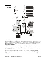
Figure 12
Blinking LED circuit.
220
Ω
Vss
P12
(916) 624-8333
www.parallaxinc.com
www.stampsinclass.com
Rev A
© 2002
X3
Vdd
Vss
Vin
P15
P14
P13
P12
P11
P10
P9
P8
P7
P6
P5
P4
P3
P2
P1
P0
X4
Code Listing
The simplest way to control a BASIC Stamp output pin is with the
HIGH
(on) and
LOW
(off) commands. Both
commands require a pin number parameter. Let's take a look at Listing 1a to see
HIGH
and
LOW
in action.
' {$STAMP BS2}
' Program: LED Blink.BS2
' Purpose: Blinks an LED connected to BASIC Stamp pin P15
' ---------------------------------------------------------------
Start:
HIGH 15 ' turn LED on
PAUSE 500 ' wait one-half second
LOW 15 ' turn LED off
PAUSE 500 ' wait one-half second
GOTO Start ' do it again
As you can see, the program starts by making pin 15 go high (5 volts). This will cause the LED to light. In order
for us to see it, though, we must insert some time before we turn it back off. We can create a short program
delay with the
PAUSE
command. Like
HIGH
and
LOW
,
PAUSE
requires a value parameter. For
PAUSE
, the value
that follows is the delay time in milliseconds (
1
/
1000
second). In our program a
PAUSE
value of 500 will allow the
LED to stay lit for one-half second.


