5.2 3D Features
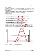
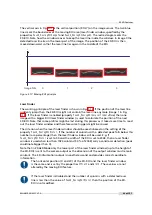
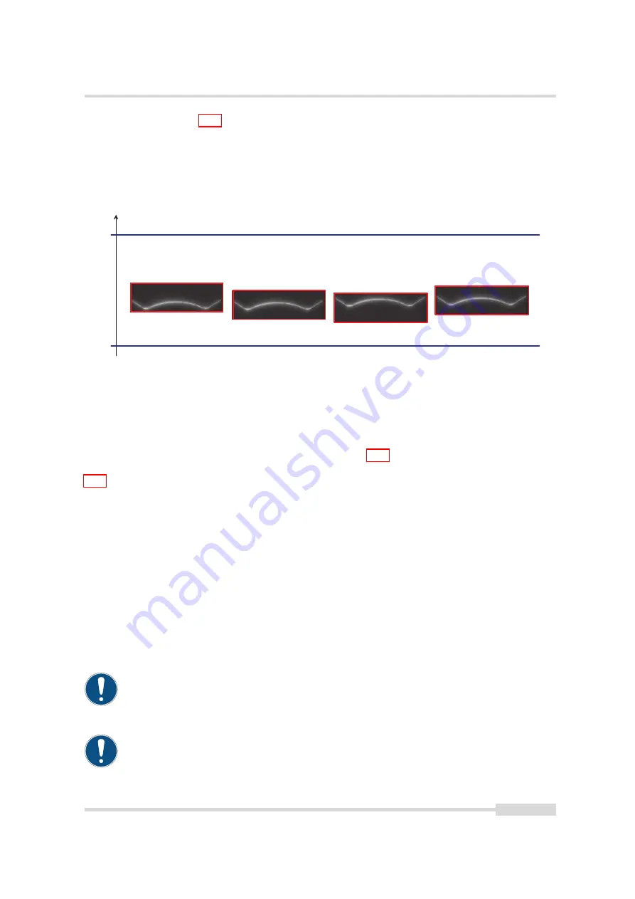
The vertical axis in Fig. 5.17 is the vertical position (ROI-Y) on the image sensor. The two blue
lines mark the boundaries of the moving ROI area (laser finder window, specified by the
properties
Peak0_MovingROIRangeY
and
Peak0_MovingROIRangeH
). The red rectangle marks the
3D-ROI. Note how the window moves to keep the laser line inside the window. In image 0 the
detected laser line lies in the lower part of the image. The position of the 3D-ROI is then
moved downward so that the laser line lies again in the middle of the ROI.
Y
0
I m a g e N b r :
1
2
3
Figure 5.17: Moving ROI principle
Laser Finder
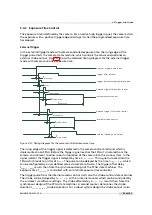
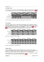
The working principle of the laser finder is shown in Fig. 5.18. If the position of the laser line
suddenly jumps then the 3D-ROI might not contain the laser line anymore (image 1 in Fig.
5.18). If the laser finder is enabled (property
Peak0_MovingROIEnLaserFinder
=True) then one
image with a bigger ROI (laser finder window) is used to calculate the position of the next
3D-ROI. Note that some profiles might be lost during this process as it takes more time to read
out the laser finder window and therefore some triggers might be missed.
The criterion when the laser finder window should be used is based on the setting of the
property
Peak0_MovingROIMinCol
. If the number of columns with a detected peak falls below this
number (as a percentage) then the laser finder window will be used. E.g. if
Peak0_MovingROIMinCol
is set to 50 and the width of the ROI is set to 2048, then a laser finder
window is used when less than 1024 columns (50 % of 2048) carry a valid laser detection (peak
coordinate bigger than 0).
Note that in 2D&3DMode only the lower part of the laser finder window (up to the height of
the 3D-ROI) is sent to the camera output as the dimension of the output window must remain
constant. The 3D information output is nonetheless valid and provides correct coordinate
information.
The horizontal position (X and W) of the 3D-ROI and the laser finder window
is the same and is set by the properties
OffsetX
and
Width
. These values are not
altered by the moving ROI feature.
If the laser finder is disabled and the number of columns with a detected laser
line is less than the value of
Peak0_MovingROIMinCol
then the position of the 3D-
ROI is not modified.
MAN075 05/2017 V1.0
49 of 127
Summary of Contents for MV1-D2048-3D06 series
Page 10: ...1 Preface 10 of 127 MAN075 05 2017 V1 0...
Page 12: ...2 Introduction 12 of 127 MAN075 05 2017 V1 0...
Page 26: ...3 How to get started 3D GigE G2 26 of 127 MAN075 05 2017 V1 0...
Page 32: ...4 Product Specification 32 of 127 MAN075 05 2017 V1 0...
Page 66: ...5 Functionality 66 of 127 MAN075 05 2017 V1 0...
Page 82: ...6 Precautions 82 of 127 MAN075 05 2017 V1 0...
Page 120: ...12 Support and Repair 120 of 127 MAN075 05 2017 V1 0...
Page 122: ...13 References 122 of 127 MAN075 05 2017 V1 0...


