background image

5 Functionality

5.4.2

Acquisition Mode

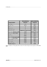
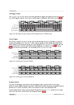
The available acquisition modes are shown in Table 5.5.

The

ContinuousRecording

and

ContinousReadout

modes can be used if more than

one camera is connected to the same network and need to shoot images si-
multaneously. If all cameras are set to Continuous mode, then all will send the
packets at same time resulting in network congestion. A better way would be to
set the cameras in

ContinuousRecording

mode and save the images in the memory

of the IPEngine. The images can then be claimed with

ContinousReadout

from one

camera at a time avoid network collisions and congestion.

AcquisitionMode

After the command AcquisitionStart is executed:

Continuous

Camera aquires image frames continuously. Acquisition can be
stopped by executing

AcquisitionStop

command.

SingleFrame

Camera acquires one frame and acquisition stops.

MultiFrame

Camera acquires n=

AcquisitionFrameCount

frames and acquisition

stops.

SingleFrameRecording

Camera saves one image on the on-board memory of the IP engine.

SingleFrameReadout

One image is acquired from the IP engine’s on-board memory. The
image must have been saved in the

SingleFrameRecording

mode.

ContinuousRecording

Camera continuosly saves images on the on-board memory of the
IP engine until the memory is full. The size of available on-board
memory is 24 MB.

ContinousReadout

All Images that have been previously saved by the

ContinuousRecording

mode are acquired from the IP engine’s

on-board memory.

Table 5.5: AcquisitionMode and Trigger

.

56 of 127

MAN075 05/2017 V1.0

Summary of Contents for MV1-D2048-3D06 series

Page 1: ...Photonfocus MV1 D2048 3D06 Camera Series 3D CMOS camera with GigE interface MAN075 05 2017 V1 0...

Page 2: ...is assumed by Photonfocus AG for its use Photonfocus AG reserves the right to make changes to this information without notice Reproduction of this manual in whole or in part by any means is prohibite...

Page 3: ...oduct Specification 27 4 1 Introduction 27 4 2 Feature Overview 29 4 3 Available Camera Models 29 4 4 Technical Specification 30 5 Functionality 33 5 1 Introduction 33 5 2 3D Features 33 5 2 1 Overvie...

Page 4: ...5 10 1 Counters 73 5 10 2 Status Information 74 5 11 Laser test image 76 5 12 Test Images 76 5 12 1 Ramp 77 5 12 2 LFSR 77 5 12 3 Troubleshooting using the LFSR 78 6 Precautions 79 6 1 IMPORTANT NOTI...

Page 5: ...108 8 11 3 PLC Settings for A B Trigger from differential inputs 109 8 11 4 PLC Settings for A B Trigger from single ended inputs 110 9 Mechanical and Optical Considerations 111 9 1 Mechanical Interfa...

Page 6: ...CONTENTS B Camera Revisions 125 B 1 General Remarks 125 B 2 Glossary of terms used in revision table 125 B 3 MV1 D2048 3D06 Revision table 126 C Revision History 127 6 of 127 MAN075 05 2017 V1 0...

Page 7: ...TRUCTIONS FOR USE BEFORE OPERATING THE CAMERA STORE THE INSTRUCTIONS FOR USE FOR FURTHER READING Photonfocus AG Bahnhofplatz 10 CH 8853 Lachen SZ Switzerland www photonfocus com info photonfocus com 4...

Page 8: ...55 451 00 00 Email support photonfocus com Table 1 1 Photonfocus Contact 1 4 Sales Offices Photonfocus products are available through an extensive international distribution network and through our ke...

Page 9: ...the reader s attention is drawn to the following icons Important note additional information Important instructions General warning possible component damage hazard Warning electric shock hazard Warni...

Page 10: ...1 Preface 10 of 127 MAN075 05 2017 V1 0...

Page 11: ...width All cameras covered in this manual use sensors with a width of 2048 pixels Sensor height This indication is optional to avoid ambiguity The cameras that use the 2 MPix CMV2000 sensor have a heig...

Page 12: ...2 Introduction 12 of 127 MAN075 05 2017 V1 0...

Page 13: ...3D Suite the GigE system should be configured as indi cated in this chapter 3 2 Hardware Installation The hardware installation that is required for this guide is described in this section The follow...

Page 14: ...ng items are included with your camera Power supply connector Camera body cap If any items are missing or damaged please contact your dealership 2 Connect the camera to the GigE interface of your PC w...

Page 15: ...ion you are asked to restart the computer please click on Yes to restart the computer before proceeding 4 After the computer has been restarted open the eBUS Driver Installation tool Start All Program...

Page 16: ...3 How to get started 3D GigE G2 Figure 3 3 PFInstaller components choice 16 of 127 MAN075 05 2017 V1 0...

Page 17: ...nal tool specific settings are described in the tool chapter 1 Open the Network Connections window Control Panel Network and Internet Connections Network Connections right click on the name of the net...

Page 18: ...ically For this quick start guide it is recommended to configure the network adapter to obtain an IP address automatically To do this select Internet Protocol TCP IP see Fig 3 4 click the Properties b...

Page 19: ...ndow that appears click on the Advanced tab and click on Jumbo Frames in the Settings list see Fig 3 6 The highest number gives the best performance Some tools however don t support the value 16128 Fo...

Page 20: ...is used then it can be switched off like this Open the Windows Firewall configuration Start Control Panel Network and Internet Connections Windows Firewall and click on the Advanced tab Uncheck the n...

Page 21: ...t appears A Properties window will open Check the eBUS Universal Pro Driver see Fig 3 8 for maximal performance Recommended settings for the Network Adapter Card are described in Section 3 4 Figure 3...

Page 22: ...EVPlayer A window with all detected devices appears see Fig 3 10 If your camera is not listed then select the box Show unreachable GigE Vision Devices Figure 3 10 GEV Device Selection Procedure displa...

Page 23: ...Ok Figure 3 12 Setting IP address 5 Finish the configuration process and connect the camera to PF_GEVPlayer 6 The camera is now connected to the PF_GEVPlayer Click on the Play button to grab images An...

Page 24: ...the status LED on the rear of the camera The status LED light is green when an image is being acquired and it is red when serial communication is active 8 Camera parameters can be modified by clicking...

Page 25: ...Figure 3 15 Control settings on the camera 9 To modify the exposure time scroll down to the AcquisitionControl control category bold title and modify the value of the ExposureTime property MAN075 05...

Page 26: ...3 How to get started 3D GigE G2 26 of 127 MAN075 05 2017 V1 0...

Page 27: ...3D mode of the camera at a reduced frame rate Global shutter Image sensor with high sensitivity Region of interest ROI freely selectable in x and y direction Column Fixed Pattern Noise Correction for...

Page 28: ...C o n v e y o r b e l t w i t h o b j e c t s L a s e r C a m e r a Figure 4 1 Triangulation principle with objects moved on a conveyor belt Figure 4 2 Photonfocus MV1 D2048 3D06 camera series 28 of...

Page 29: ...Noise Correction for improved image quality Isolated inputs 2 single ended 2 differential and outputs 2 single ended Trigger input Strobe output with programmable delay A B shaft encoder interface RS...

Page 30: ...models 390 to 670 nm to 10 of peak responsivity Conversion gain 0 075 LSB e Sensitivity 5 56 V lux s with micro lenses 550 nm Optical fill factor 42 without micro lenses Dark current 125 e s 25 C Dyn...

Page 31: ...ensions 55 x 55 x 51 5 mm3 Mass 260 g Conformity CE RoHS WEEE Table 4 4 Physical characteristics and operating ranges Footnotes 1 for minimal camera power consump tion work with a power supply at 12V...

Page 32: ...4 Product Specification 32 of 127 MAN075 05 2017 V1 0...

Page 33: ...tion is determined by the scattering of the material to be inspected There are setups for highly scattering materials and others for nearly reflecting surfaces In addition the penetration depth of lig...

Page 34: ...benefit of little occlusions Camera Line Laser Figure 5 1 Triangulation setup 1 Triangulation Setup 2 This setup shows an opposite configuration of the laser line and the camera The resolution at sam...

Page 35: ...e used as signal for triangulation Also in this case this triangulation setup helps to get results C a m e r a L i n e L a s e r Figure 5 3 Triangulation setup 3 Triangulation Setup 4 In contrast to s...

Page 36: ...dth threshold around the laser peak If there are no pixels at the peak position that are above the width threshold the resulting laser line width is 0 In this case the width threshold value should be...

Page 37: ...ng in pixel accuracy or the thresholding of the Gaussian and calculation of the average resulting in sub pixel accuracy The nonlinear interpolation technique used in the LineFinder algorithm results i...

Page 38: ...l a t i o n P i x e l S u b p i x e l r o t a t e d b y 9 0 G a u s s i a n s h a p e d c r o s s s e c t i o n o f a l a s e r l i n e Figure 5 6 Interpolation technique provides sub pixel accuracy...

Page 39: ...of 3D data which are always placed in the 8 LSB A table with the bit assignment of the 3D data for DataFormat3D 2 is shown in Fig 5 7 DataFormat3D 3 in Fig 5 8 and DataFormat3D 4 in Fig 5 9 Note that...

Page 40: ...i n f o r m a t i o n Figure 5 8 3D data format DataFormat3D 3 3 D r o w 7 6 5 4 3 2 1 0 B i t s D e s c r i p t i o n 0 P E A K 1 5 8 D e t e c t e d l a s e r l i n e c o o r d i n a t e P E A K 1...

Page 41: ...ue lies between 0x800 2048 and 0x8ff 2303 P o s i t i o n i n t e g r a l p a r t P o s i t i o n f r a c t i o n a l p a r t L a s e r l i n e w i d t h L L _ H E I G H T 3 D r o w 7 6 5 4 3 2 1 0 B...

Page 42: ...me rate For FrameCombine f the data for f images are combined into one image Resulting height in 3Donly mode is therefore Hres f 4 if DataFormat3D 3 or 4 or Hres f 2 if DataFormat3D 2 0 0 W 3 D d a t...

Page 43: ...can be set by the user This value should be set so that the resulting frame rate is well below 1000 fps e g at 100 fps E g if the camera shows a maximal frame rate of 4000 property AcquisitionFrameRat...

Page 44: ...he timeout occured after the second frame and the two remaining frames are filled with dummy data DataFormat3D 2 is used in this example The FrameCombine mode is only available in 3Donly mode When acq...

Page 45: ...ightMax see Fig 5 8 and Fig 5 15 Peak0_PeakFilterWidthMin Filters all peaks columns where LL_WIDTH Peak0_PeakFilterWidthMin see Fig 5 8 and Fig 5 16 Peak0_PeakFilterWidthMax Filters all peaks columns...

Page 46: ...d i r e c t i o n T h r e s h o l d W i d t h T h r e s h o l d P e a k F i l t e r W i d t h M a x o k f i l t e r e d w i d t h t o o b i g f i l t e r e d w i d t h t o o s m a l l Figure 5 16 Illu...

Page 47: ...useful if the 3D ROI is not kept constant Example Peak0_EnAbsCoordinate True Peak0_3DY 200 If the peak is detected in row 50 of the ROI the value 250 50 Peak0_3DY would be given as resulting 3D coordi...

Page 48: ...RangeH Height of the laser finder window The ROI is only moved inside the window specified by MovingROIRangeY and MovingROIRangeH Peak0_MovingROIMinCol Minimal percentage of columns detected peaks req...

Page 49: ...t takes more time to read out the laser finder window and therefore some triggers might be missed The criterion when the laser finder window should be used is based on the setting of the property Peak...

Page 50: ...smoothing which results in the highest amount of smoothing Columns where no position is determined are simply skipped when calculating the moving average meaning the 8 or 16 previous positions that w...

Page 51: ...be fully contained in the laser finder window even if the laser finder feature is disabled this is not enforced by the software 5 Set the value of Peak0_MovingROIMinCol even if you are not using lase...

Page 52: ...0 x 768 WXGA 60 fps 800 x 600 SVGA 77 fps 640 x 480 VGA 96 fps 2048 x 256 178 fps Table 5 2 Frame rates of different ROI settings in 2Donly mode minimal exposure time 5 3 2 Region of Interest ROI in 3...

Page 53: ...nt ROI settings in different 3D modes DataFor mat3D 2 minimal exposure time free running mode Peak0_3DH 2D 3D mode 3Donly mode 3Donly mode HS 11 2496 fps 14146 fps 14146 fps 16 1968 fps 14146 fps 1414...

Page 54: ...cquisitionFrameRate Software Trigger The trigger signal is applied through a software command TriggerSoftware in category AcquisitionControl Settings for Software Trigger mode TriggerMode On and Trigg...

Page 55: ...5 4 Trigger and Strobe Figure 5 19 Trigger source Figure 5 20 Trigger Inputs Multiple GigE solution MAN075 05 2017 V1 0 55 of 127...

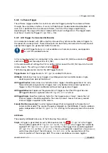
Page 56: ...executed Continuous Camera aquires image frames continuously Acquisition can be stopped by executing AcquisitionStop command SingleFrame Camera acquires one frame and acquisition stops MultiFrame Came...

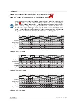
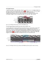
Page 57: ...t t r i g g e r o f f s e t t s t r o b e o f f s e t Figure 5 21 Timing diagram for the camera controlled exposure time The rising edge of the trigger signal is detected in the camera control electro...

Page 58: ...e Off 5 4 6 Burst Trigger The camera includes a burst trigger engine When enabled it starts a predefined number of acquisitions after one single trigger pulse The time between two acquisitions and the...

Page 59: ...o n t r o l i n t e r n a l s t r o b e c o n t r o l e x t e r n a l s t r o b e p u l s e o u t p u t t d i s o i n p u t t j i t t e r t t r i g g e r d e l a y t e x p o s u r e t s t r o b e d e...

Page 60: ...non burst mode 170 ns duration of 1 row ttrigger offset burst mode 210 ns 210 ns texposure 13 s 0 34 s tstrobe delay 600 ns 0 34 s tstrobe offset non burst mode 170 ns 170 ns tstrobe offset burst mod...

Page 61: ...single double quad see description below ABTriggerDirection Determines in which direction a trigger should be generated fwd only forward movement generates a trigger bkwd only backward movement genera...

Page 62: ...the single trigger mode but without the bug use the double A B mode and double the value of ABTriggerDivider A B G r a y C o u n t e r E n c o d e r C o u n t e r T r i g g e r F w d T r i g g e r B...

Page 63: ...belt stops and retraces by a small amount which may cause a misalignment in the system If ABTriggerDirection fwd is used and the Debounce mode is enabled and the conveyor belt starts again in forward...

Page 64: ...s enabled then the encoder position is always incremented Detailed diagrams are shown in Fig 5 29 and Fig 5 30 Note that the quad mode is not available when ABTriggerAOnly true A E n c o d e r C o u n...

Page 65: ...of an active edge of the reset source without the requirement to arm the device first This setting is suited if the reset source signal is different than the camera trigger The active edge of the rese...

Page 66: ...5 Functionality 66 of 127 MAN075 05 2017 V1 0...

Page 67: ...uses ISO_IN0 as trigger enable signal the inverted signal is used as ISO_IN0 is inverted in the input logic see Fig 8 4 T r i g g e r A c q u i s i t i o n _ S t a r t T r i g g e r I n A p p l i e d...

Page 68: ...b l e d i s a b l e d e n a b l e d d i s a b l e d Figure 5 32 Trigger Acquisition Level triggered TriggerAcquisition_Mode Edge Trigger Acquisition and Free Running Trigger The TriggerAcquisition fe...

Page 69: ...Multislope_NrSlopes 3 3 slopes with knee points A and B Multislope_Value1 Corresponds to Vlow1 the higher the value the higher the compression Multislope_Time1 Time corresponding to knee point B The v...

Page 70: ...e e p o i n t A K n e e p o i n t B M u l t i s l o p e _ T i m e 2 M u l t i s l o p e _ T i m e 1 E x p o s u r e T i m e Figure 5 33 Multi Slope HDR mode n u m b e r o f e l e c t r o n s S a t u...

Page 71: ...is shown in figure Fig 5 35 I m a g e S e n s o r D i g i t a l O f f s e t D i g i t a l G a i n L i n e F i n d e r I m a g e o u t p u t T e s t i m a g e s i n s e r t i o n r a m p L F S R L a s...

Page 72: ...of the grey values of its two neighbours on the same row B l a c k P i x e l C o r r e c t i o n R a w i m a g e I n t e n s i t y B l a c k L i m i t D i f f L e f t D i f f R i g h t D i f f L e f...

Page 73: ...nd if the brightness of the image is too big then the interesting part of the output image might be saturated By subtracting an offset from the input of the gain block it is possible to avoid the satu...

Page 74: ...formation Status information is inserted in the 4 LSB in the last 3D data row if DataFormat3D 3 or 4 see bits labeled STAT in Fig 5 8 LSB are transmitted first see Table 5 8 The status information is...

Page 75: ...5 2 14 value 0 there are more columns with a detected laser line than specified in Peak0_MovingROIMinCol Value 1 there are less columns with a detected laser line than specified in Peak0_MovingROIMinC...

Page 76: ...ensor They can be used to check the transmission path from the camera to the acquisition software Independent from the configured grey level resolution every possible grey level appears the same numbe...

Page 77: ...with a pseudo random grey level sequence containing every possible grey level that is repeated for every row The LFSR test pattern was chosen because it leads to a very high data toggling rate which s...

Page 78: ...random test pattern containing all grey levels If the data transmission is correctly received the histogram of the image will be flat Fig 5 40 On the other hand a non flat histogram Fig 5 41 indicates...

Page 79: ...t use camera power supplies which meet the Limited Power Source LPS requirements If you use a powered hub or a powered switch in PoE or USB vision systems these devices must meet the LPS requirements...

Page 80: ...e is available on the Photonfocus website www photonfocus com To ensure that the examples will work properly in your application you must adjust them to meet your specific needs and must carefully tes...

Page 81: ...nts or thinners which can damage the surface the serial number label and electronic parts Avoid the generation of ESD during cleaning Take only a small amount of detergent to clean the camera body Kee...

Page 82: ...6 Precautions 82 of 127 MAN075 05 2017 V1 0...

Page 83: ...tes camera operation E t h e r n e t J a c k R J 4 5 P o w e r S u p p l y a n d I O C o n n e c t o r S t a t u s L E D Figure 7 1 Rear view of the GigE camera 7 2 Power Supply Connector The camera r...

Page 84: ...S cameras LED Green It blinks slowly when the camera is not grabbing images When the camera is grabbing images the LED blinks at a rate equal to the frame rate At slow frame rates the LED blinks At hi...

Page 85: ...C 0 _ P I S O _ I N C 0 _ N I S O _ I N C 1 _ P I S O _ I N C 1 _ N I S O _ I N 0 I S O _ I N 1 I S O _ O U T 0 I S O _ O U T 1 I s o l a t e d I n t e r f a c e C a m e r a E l e c t r o n i c I S O...

Page 86: ...C 0 _ N I S O _ I N C 1 _ P I S O _ I N C 1 _ N I S O _ I N 0 I S O _ I N 1 I S O _ O U T 0 I S O _ O U T 1 I s o l a t e d I n t e r f a c e C a m e r a E l e c t r o n i c I S O L A T O R I S O _ G...

Page 87: ...e power supply within a range between 10 and 30V In the same way encoder ground HTL_ENC_GND and ISO_GND signals should be connected to the same ground in order to guarantee the good reception of the d...

Page 88: ...O S F E T I S O _ O U T 0 P T C 4 k 7 M a x 3 0 V M a x 0 5 A M a x 0 5 W I S O _ G N D P o w e r M O S F E T I S O _ O U T 1 P T C M a x 3 0 V M a x 0 5 A M a x 0 5 W I s o l a t e d I n t e r f a c...

Page 89: ...M O S F E T I S O _ O U T 0 P T C 4 k 7 M a x 3 0 V M a x 0 5 A M a x 0 5 W I S O _ G N D P o w e r M O S F E T I S O _ O U T 1 P T C M a x 3 0 V M a x 0 5 A M a x 0 5 W I s o l a t e d I n t e r f a...

Page 90: ...e r F E T 4 7 V 1 0 k I S O _ I N 0 C a m e r a 7 1 2 p o l H i r o s e C o n n e c t o r I S O _ G N D 1 2 Y O U R _ G N D Y O U R _ G N D I n p u t V o l t a g e M a x 3 0 V D C M i n 3 0 V D C Fig...

Page 91: ...E T I S O _ O U T 0 P T C 4 k 7 C a m e r a 3 1 2 p o l H i r o s e C o n n e c t o r I S O _ G N D 1 2 Y O U R _ G N D I S O _ P W R Y O U R _ P W R Y O U R _ G N D C o n t r o l L o g i c Y O U R _...

Page 92: ...o ISEO_OUT1 Max imal ratings that must not be exceeded voltage 30 V current 0 5 A power 0 5 W see also Fig 7 11 The type of the Power MOSFET is International Rectifier IRLML0100TRPbF Y O U R _ P W R I...

Page 93: ...e r a Figure 7 12 Incorrect connection to ISO_INC inputs 7 6 5 Master Slave Camera Connection The trigger input of one Photonfocus G2 camera can easily connected to the strobe output of another Photon...

Page 94: ...D CAM_PWR Using a common power supply for camera and I O signals with star wiring Separate Grounds To separate the signal and ground connections of the camera CAM_GND CAM_PWR data connections from the...

Page 95: ...tic of the star wiring concept applied to a Photonfocus GigE camera The power supply and ground connections for the camera and for the I O are connected to the same power supply which acts as the Star...

Page 96: ...ow the power and ground cables are connected to the same power supply P o w e r S u p p l y C a m e r a F l a s h M a c h i n e V i s i o n S y s t e m P C E t h e r n e t D a t a C a b l e S T R C A...

Page 97: ...S O _ G N D t h e w r o n g w a y G r o u n d l o o p G r o u n d l o o p Figure 7 18 Improper I O wiring causing a ground loop 7 7 PLC connections The PLC Programmable Logic Controller is a powerful...

Page 98: ...A5 camera head PLC LVAL Line Valid signal A6 camera head PLC DVAL Data Valid signal A7 camera head PLC Reserved CL_SPARE Q0 PLC not connected Q1 PLC power connector ISO_OUT1 output signal signal is in...

Page 99: ...be configured by a Graphical User Interface GUI tool for Gigabit Ethernet Vision cameras or they can be programmed with custom software using the SDK A GUI tool that can be downloaded from Photonfocus...

Page 100: ...of the camera head IP properties and properties of the PLC Programmable Logic Controller see also Section 7 7 and document PLC Image stream control Set image stream properties and display image stream...

Page 101: ...the control window to apply the property value to the camera A red cross at the upper right corner of the GEV Control Window indicates a parameter error i e a parameter is not correctly set In this ca...

Page 102: ...equally e g a special grey reference card while clicking on the White Balance button The white balance settings that were made as described in this section are ap plied by the PF_GEVPlayer software an...

Page 103: ...e 8 4 Frequently used properties The following list shows some frequently used properties that are available in the Beginner mode The category name is given in parenthesis Width ImageFormatControl Wid...

Page 104: ...mes should be set to 20 or more 7 If FrameCombine is used then the parameter FrameCombine_Timeout in microseconds should be set see also Section 5 2 9 The value should be higher than the longest time...

Page 105: ...esn t show 0 after various tries check if the camera receive triggers or set the TriggerMode of the camera to Off 9 Check the values of the properties ColCorrection_Overflow and ColCorrection_Underflo...

Page 106: ...ettings in the non volatile flash memory At power up these values are loaded The property UserSetSave in category UserSetControl overwrites the current camera settings with the settings that are store...

Page 107: ...T a b l e I 1 I 2 I 3 I 4 I 5 I 6 I 7 I 0 E n h a n c e d F u n c t i o n B l o c k Q 0 Q 1 Q 2 Q 3 Q 4 Q 5 Q 6 Q 7 Q 8 Q 9 Q 1 0 Q 1 1 Q 1 5 Q 1 6 Q 1 7 R e m o t e C o n t r o l B l o c k f r o m h...

Page 108: ...by setting the PLC_Q4_Variable to Zero and the PLC_Q4_Operator to Or for inputs 1 to 3 5 If a PLC output is used to connect to a camera trigger then the corresponding Trigger Source must be activated...

Page 109: ...ock PLC_I3 Line3 PLC SignalRoutingBlock PLC_Q6_Variable0 PLC_I2 PLC LookupTable Q6 PLC_Q6_Operator0 Or PLC LookupTable Q6 PLC_Q6_Variable1 Zero PLC LookupTable Q6 PLC_Q6_Operator1 Or PLC LookupTable Q...

Page 110: ...I1 Line1 PLC SignalRoutingBlock PLC_Q6_Variable0 PLC_I0 PLC LookupTable Q6 PLC_Q6_Operator0 Or PLC LookupTable Q6 PLC_Q6_Variable1 Zero PLC LookupTable Q6 PLC_Q6_Operator1 Or PLC LookupTable Q6 PLC_Q6...

Page 111: ...of the camera housing for the Photonfocus D L2048 GigE camera series 55 55 20 12 8 25 4 36 6 41 3 5 51 5 8x M5 60 8 Figure 9 1 Mechanical dimensions of the Photonfocus 2048 GigE cameras 20 41 8 36 9...

Page 112: ...ht edge line in a distance x x infinite distance of your lens from the camera e g a door frame 5 Screw the ring upwards or downwards until the straight edge line distance infinite is also straight on...

Page 113: ...ce as described below Examples of suitable lens cleaning materials are given in Table 9 1 Cleaning materials must be ESD safe lint free and free from particles that may scratch the sensor surface Do n...

Page 114: ...340 Q tips Hans J Michael GmbH Germany Methanol Fluid Johnson Matthey GmbH Germany Semiconductor Grade 99 9 min Assay Merck 12 6024 UN1230 slightly flammable and poisonous www alfa chemcat com 2 Prop...

Page 115: ...eld immunity test EN 61000 4 4 2012 Electrical fast transient burst immunity test EN 61000 4 5 2014 Surge immunity test EN 61000 4 6 2014 Immunity to conducted disturbances induced by radio frequency...

Page 116: ...s set out in Radio Interference Regulations 10 2 3 Pour utilisateurs au Canada Cet appareil est conforme aux normes Classe A pour bruits radio lectriques sp cifi es dans le R glement sur le brouillage...

Page 117: ...sure that your warranty remains in force adhere to the following rules 1 Do not open the housing or destroy the warranty seal of the camera Touching internal electronic components of the camera may da...

Page 118: ...ctions in the corresponding chapter of this manual 9 Transport and store the camera in its original packaging only and protect the sensor and the lens mount with a camera body cap 10 Read the manual c...

Page 119: ...he Photonfocus sales team via email sales photonfocus com 12 2 Repair and obtaining an RMA Number Whenever you want to return a camera to Photonfocus contact first the Photonfocus support to be sure t...

Page 120: ...12 Support and Repair 120 of 127 MAN075 05 2017 V1 0...

Page 121: ...t Guide Pleora Technologies Included in eBUS installer MAN051 Manual Photonfocus GigE Quick Start Guide Photonfocus MAN053 Manual PF 3D Suite Photonfocus included in the PFInstaller PLC iPORT Programm...

Page 122: ...13 References 122 of 127 MAN075 05 2017 V1 0...

Page 123: ...correct voltages will damage or destroy the camera The connection of the input and output signals is described in Section 7 6 A suitable power supply can be ordered from your Photonfocus dealership Co...

Page 124: ...ly 5V 24V for output signals Do NOT connect to camera Power 7 I ISO_IN0 IN0 input signal 8 O ISO_OUT1 MISC Q1 output from PLC no Pull up to ISO_PWR can be used as additional output by adding Pull up o...

Page 125: ...t least 5 digits The two rightmost digits are the build number the next two digits counting from the right side are the minor revision number and the remaining digits are the major revision number uCR...

Page 126: ...5 2 10 yes Absolute coordinates Section 5 2 12 yes High speed mode Section 5 2 13 yes Moving ROI Section 5 2 14 yes Standard trigger yes A B trigger Section 5 4 9 yes External counter reset Section 5...

Page 127: ...C Revision History Revision Date Changes 1 0 May 2017 First version MAN075 05 2017 V1 0 127 of 127...

Reviews: