background image

Page 18 

P R A X S Y M    

Errors 

 
Either host or PathTrax unit will discard a packet if it contains an 

error. The PathTrax Transmitter and Receiver will respond 

differently to a packet with an error using a code to help identify 
the source of the error. If the host receives a packet that contains 

an error, it must re-issue a command to obtain the desired 

response.  Error response codes are listed below: 
 

Invalid commands sent to the PathTrax Receiver will be 

acknowledged with an error response.  An error response will 
consist of 4 ASCII bytes followed by a carriage return.  The error 

code consists of the two characters ER followed by a two-character 

error status code. 



ERIC<CR> Invalid command 


The command was not recognized.  Verify the command you 


are sending is valid. 



ERIN<CR> Invalid number or range 


The data included in the previous command was invalid or 

 out 

of 

range. 



ERIM<CR> Incompatible Mode for command 


The command was not recognized because it was entered in 


an incompatible mode. 



ERNI<CR> Not Initialized, Shield Level not available 


Response to the “SL?” query when the Receiver has not been 


initialized with the Transmitter. 


User Commands 


Note:  The under score “_” indicates a space (hex 20) is sent in the 

command    

Note: <CR> indicates that the user should press the “enter” key. 
 

Receiver Commands 

 
SS?<CR> 


Returns the last measured signal strength 


in the form (-)XXX (dBm) for the current 

 band. 


Example: -70 


SL?<CR>  

Returns the last measured shield level in the 
form XXX (dB) for the current frequency.  


Example: 103 

Summary of Contents for Pathtrax 500

Page 1: ...User s Manual The solution for making easy shielding effectiveness measurements PathTrax...

Page 2: ...r agrees to repair or replace at its discretion any failure which upon PRAXSYM s inspection appears to be a result of workmanship or material defect In no case shall PRAXSYM s liability for breach of...

Page 3: ...a top mounted controls or through the USB port provided Complete control of the unit s operation can be accomplished via the serial port with the exception of power ON OFF and receiver volume Measurem...

Page 4: ...ing Step Size 1 MHz 100 kHz and 10 kHz Operating Modes Signal Strength Spectrum Monitor Path Loss Shield Level IF Bandwidth 15 kHz nominal 1st IF 90 MHz 2nd IF 450 kHz RF Input Connector TNC Female BN...

Page 5: ...E FINE THOLD sets threshold for go no go testing LOCK locks out control panel MODE SIGNAL STRENGTH SPECTRUM MONITOR PATH LOSS and SHIELD LEVEL and CAL provides path loss or shielding reference level n...

Page 6: ...infinite VSWR RF Output Connector TNC Female BNC on Pathtrax 500 Battery Operation 2 hours minimum at full charge Batteries Nickel Cadmium 9 6V 1800 mAh AC Charger Operation 95 265 VAC 48 65 Hz Charge...

Page 7: ...button initiates the internal System Calibration sequence See OPERATION section for details THOLD These two buttons increment the threshold value up or down The value is displayed on the LCD This is t...

Page 8: ...t level as set by the F DIGIT button ATTEN Pressing the ATTEN button changes the power output level in 10 dB steps from 30 to 30 dBm The current power level is displayed on the LCD screen Press the AT...

Page 9: ...of narrow band modulated signals The signal strength is displayed on the LCD display in dBm decibels relative to 1 mW The receiver is calibrated at the time manufacture by applying signals of known le...

Page 10: ...S mode can be used to measure the amount of attenuation path loss between the transmitter and receiver Before making path loss measurements the receiver is initialized with the transmitter to obtain a...

Page 11: ...knob to tune the receiver in the selected step size Setting the Receiver Tone Threshold The receiver contains an audio tone generator that can be used to alert the operator if a shield level has drop...

Page 12: ...The attenuation level always increases in 10 dB steps and to the next even 10 dB amount For example if the attenuator has been set at 13 dB using the rotary control in ATTEN mode pressing the ATTN but...

Page 13: ...to 60 dB and allow both units to warm up for 5 minutes With the receiver in SIGNAL STRENGTH mode monitor the test frequency to insure no interfering signal is present on your test frequency Place the...

Page 14: ...e test frequency to insure no interfering signal is present on your test frequency Place the transmitter inside the enclosure on a marked reference position near the center of the enclosure Place the...

Page 15: ...the following steps 1 Insert the plug of the AC DC 15 V adapter into the recharge receptacle on the right side of the PathTrax Transmitter or Receiver Plug the charger line cord into an AC source 95...

Page 16: ...full and no charging will take place This condition is dependent on many factors including battery age battery charge time since last charge termination and charger voltage and therefore might not occ...

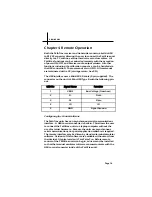
Page 17: ...following pin out Configuring the Control Software The PathTrax units have an asynchronous serial communications interface A USB to serial converter is built in This allows the user to connect the Pa...

Page 18: ...may be found in various places depending on the terminal emulation software used Data Link Layer Description Transmission Packet The transmission packet consists of a series of ASCII characters capita...

Page 19: ...r error status code ERIC CR Invalid command The command was not recognized Verify the command you are sending is valid ERIN CR Invalid number or range The data included in the previous command was inv...

Page 20: ...urn battery voltage note the BATT on the display begins to flash at 8 40 volts Example BA 08 60 VR CR Returns version Example PATHTRAX TX Vx xx Transmitter Commands FR XXX yy CR Set the frequency to X...

Page 21: ...ns battery voltage Example BA 09 60 LC CR Local mode place the front panel in control OK RM CR Remote mode locks the front panel OK AT_XX CR Sets attenuation XX is decimal number between 0 and 60 OK A...

Page 22: ...nications port This enables the product to be controlled by any PC or laptop with a USB V1 1 or V2 0 interface When used by the user in normal operation the USB interface mimics RS 232 serial communic...

Page 23: ...Page 22 Notes...

Page 24: ...900 000005 001 Rev E...

Reviews: