502 069 02
42/79
Power Monitor, PD 3260
Manual
Variables on Generator Switch channel.
Channel identifier: GeneratorSwitch
SWNo
Identifier
Memory type
Read out
Type
SI Unit
B0
FlagReg
RAM Read Write
Binary
Array
- - -
B1
Phase
RAM Read Write
Decimal
Real
(
B2
PhaseSpeed
RAM Read Write
Decimal
Real
(/s
B3
PhaseAcc
RAM Read Write
Decimal
Real
(/s/s
B4
B5
B6
B7
B8
B9
ChConfig
EEPROM RPW
- - -
Record
- - -
BA
TachoScale
EEPROM RPW
Decimal
Real
[]
BB
StartSpeed
EEPROM RPW
Decimal
Real
(/s
BC
DelayComp
EEPROM RPW
Decimal
Real
s
BD
Maintenance
EEPROM RPW
- - -
Record
- - -
BE
ChType
PROM Read Only
- - -
Record
- - -
BF
ChError
RAM Read Only
Binary
Record
- - -
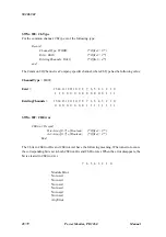
SWNo $B0: FlagReg.
7 6 5 4 3 2 1 0
SwitchEnable
OutFlag
Not used
Not used
Not used
Not used
Not used
Not used
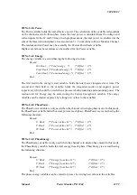
Bit 7: SwitchEnable.
The start function is enabled by setting SwitchEnable = True. When the switching conditions are
satisfied, the OutFlag is set, and the controlled output channel is switched on. The Outflag is reset
and the controlled output is switched off, by setting SwitchEnable = False.
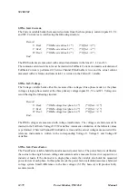
Bit 6: OutFlag.
OutFlag indicates the actual status of the output function. If a digital I/O channel is selected in
Ref_A, OutFlag controls the OutFlag of this digital I/O channel.

