


Designer’s
Handbook
21
directives
to decide where to place code and data in logical memory and its mapping to
physical
memory through a segment register value. The directives are normally specified
in
the BIOS. However, the directives may also be useful in the user program for certain
tasks
such as compiling a pilot BIOS or coldloader, or special situations where a user
wants
two application coresident within a single 256K quadrant of flash.
Each
origin statement has the following syntax:
#<origin type> <origin name> <segment value> <logical address>
<size> apply
All
of the arguments are required.
<
origin type
>
may be one of the following:
rcodorg, xcodorg, wcodorg,
rvarorg
,
and
wvarorg
.
These origin types define where to place root code, extended
code,
watch code, root data, and watch data, respectively. The code origin directives grow
up
(increase) whereas the data origins grow down (decrease). Origin directives should be
defined
before code or data of the associated type is compiled. For example, any data dec-
larations
or code should appear after the
rcodorg
and
rvarorg
directives. Likewise,
xcodorg
statement should appear before any code is compiled to xmem.
<
origin name
>
creates an identifier associated with that particular directive.
<
segment value
>
should be an 8-bit value segment value for the origin segment. The
physical
address can be calculated by shifting the <
segment value
>
to the left by 12
bits
and adding the 16-bit <
logical address
>
value.
<
size
>
tells the compiler when to issue an “out of space” error for that directive when
the
code counter grows out of bounds.
apply
means that the org statement will take effect immediately. This is required for all
org
statements. Future releases may allow different keywords to be used in place of the
apply
argument.
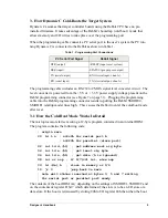
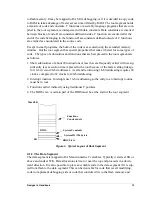
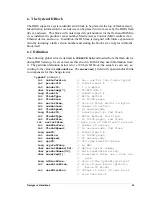
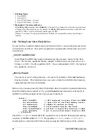
Examples
An
typical example of using the origin directives in the BIOS is shown below. The dia-
gram
below shows how the origin statements define the mapping between the logical and
physical
address spaces.
#define DATASEGVAL 0x91
#rvarorg rootdata
(DATASEGVAL) 0xc5ff 0x6600
apply // grows down
#rcodorg rootcode
0x00
0x0000 0x6000
apply
#wcodorg watcode
(DATASEGVAL) 0xc600 0x0400
apply
#wvarorg watdata
(DATASEGVAL) 0xcdff 0x0400
apply // grows down
#xcodorg xmemcode
0xf8
0xe000 0x1a000 apply
// data declarations start here
Summary of Contents for 2000
Page 1: ...Rabbit 2000 Microprocessor Designers Handbook Revision C...
Page 4: ...Rabbit 2000 Microprocessor...
Page 6: ...2 Rabbit 2000 Microprocesssor...
Page 12: ...8 Rabbit 2000 Microprocessor...
Page 34: ...344 Dynamic C User s Manual...
Page 36: ...34 Rabbit 2000 Microprocessor...
Page 44: ...42 Rabbit 2000 Microprocessor...


