


RTD Embedded Technologies, Inc.
| www.rtd.com
38
DM35418HR/DM35218HR
User’s Manual
BDM-610010041 Rev F
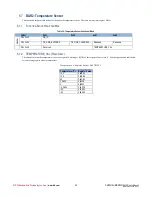
6.2.4
FB_DMA
M
_S
TAT
_U
SED
(R
EAD
/W
RITE
)
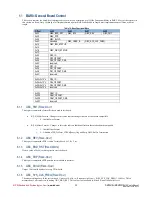
This register is used to determine the source of a DMA interrupt. The bits are cleared by writing 0x00 to the byte. Stat_Used will be set
regardless of having ErrIntEna set to ‘1’, and regardless of the state of the IgnoreUsed bit (above).
B0: Used_Desc (R/C). Set to ‘1’ by the DMA engine if it attempting to use a descriptor with the
bit set.
6.2.5
FB_DMA
M
_S
TAT
_I
NVALID
(R
EAD
/W
RITE
)
This register is used to determine the source of a DMA interrupt. The bits are cleared by writing 0x00 to the byte. Stat_Invalid will be set
regardless of having ErrIntEna set to ‘1’.
B0: Invalid_Desc (R/C). Set to ‘1’ by the DMA engine if it attempting to use a descriptor with the
bit cleared.
6.2.6
FB_DMA
M
_S
TAT
_O
VERFLOW
(R
EAD
/W
RITE
)
This register is used to determine the source of a DMA interrupt. The bits are cleared by writing 0x00 to the byte. Stat_Overflow will be set
regardless of having ErrIntEna set to ‘1’.
B0: Overflow (R/C). Set to ‘1’ by the DMA engine if an overflow occurred on the FIFO.
6.2.7
FB_DMA
M
_S
TAT
_U
NDERFLOW
(R
EAD
/W
RITE
)
This register is used to determine the source of a DMA interrupt. The bits are cleared by writing 0x00 to the byte. Stat_Underflow will be set
regardless of having ErrIntEna set to ‘1’.
B0: Underflow (R/C). Set to ‘1’ by the DMA engine if an underflow occurred on the FIFO.
6.2.8
FB_DMA
M
_S
TAT
_C
OMPLETE
(R
EAD
/W
RITE
)
This register is used to determine the source of a DMA interrupt. The bits are cleared by writing 0x00 to the byte.
B0: Buffer_Complete (R/C). Set to ‘1’ by the DMA engine when a buffer is filled that has the
bit set.
6.2.9
FB_DMA
M
_C
URRENT
_B
UFFER
(R
EAD
-O
NLY
)
This is the ID for the buffer that will be used for the next access. The driver may use this to track the progress of the DMA activity.
6.2.10
FB_DMA
M
_COUNT
(R
EAD
-O
NLY
)
This is the offset in the DMA buffer for the next access. The driver may use this to track the progress of the DMA activity.
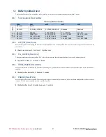
6.2.11
FB_DMA
M
_RD_FIFO_CNT(R
EAD
-O
NLY
)
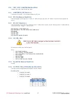
B[9:0] This is the amount of data available in the read FIFO in bytes. Software can use this to determine when the FIFO is empty. A
value of 0x3FC indicates that there are 1020 or more bytes available.
B15: RD_EMPTY- ‘1’ indicates that the read FIFO is empty
6.2.12
FB_DMA
M
_WR_FIFO_CNT(R
EAD
-O
NLY
)
B[9:0] This is the amount of space available in the write FIFO in bytes. Software can use this to determine when the FIFO is empty.
A value of 0x3FC indicated that there are 1020 or more bytes available.
B15: WR_FULL- ‘1’ indicates that the read FIFO is full
6.2.13
FB_DMA
M
_ADDRESS
N
(R
EAD
/W
RITE
)
This is the 64-bit PCI address for DMA Channel m, buffer n. It must be double-word aligned (i.e. b[1:0] are reserved).
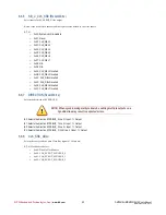
6.2.14
FB_DMA
M
_SIZE
N
(R
EAD
/W
RITE
)
This is the size in bytes of the buffer for DMA Channel m, buffer n. It must be an integer number of double-words (i.e. b[1:0] are reserved). The
actual size is FB_DMAm 4 Bytes. The maximum buffer size is 16MB.


