Copyright
c
2016, SiFive Inc. All rights reserved.
11
To save power, the HFROSC can be disabled by clearing
hfroscen
. The processor must be
running from a different clock source (the PLL, external crystal, or external clock) before disabling
HFROSC. HFROSC can be explicitly renabled by setting
hfroscen
. HFROSC will be automatically
re-enabled at every reset.
The status bit
hfroscrdy
indicates if the oscillator is operational and ready for use as a clock
source.
External 16 MHz Crystal Oscillator (HFXOSC)
An external high-frequency 16 MHz crystal oscillator can be used to provide a precise clock source.
The crystal oscillator should have a capacitive load of
≤
12 pF and an ESR
≤
80
Ω
.
When used to drive the PLL, the 16 MHz crystal oscillator output frequency must be divided by two
in the first-stage divider of the PLL (i.e.,
R
= 2
) to provide an 8 MHz reference clock to the VCO.
The input pad of the HFXOSC can also be used to supply an external clock source, in which case,
the output pad should be left unconnected.
The HFXOSC input can be used to generate
hfclk
directly if there is no PLL present in the system,
or if the PLL is set to bypass.
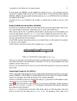
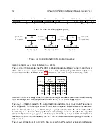
The HFXOSC is controlled via the memory-mapped
hfxosccfg
register.
31
30
29
0
hfxoscrdy
hfxoscen
0
1
1
30
Table 4.2: The HFXOSC config register,
hfxoscccfg
.
The
hfxoscen
bit turns on the crystal driver and is set after wakeup reset, but can be cleared to
turn off the crystal driver and reduce power consumption. The
hfxoscrdy
bit indicates if the crystal
oscillator output is ready for use.
The
hfxoscen
bit must also be turned on to use the HFXOSC input pad to connect an external
clock source.
Internal High-Frequency PLL (HFPLL)
The PLL generates a high-frequency clock by multiplying a mid-frequency reference source clock,
either the HFROSC or the HFXOSC. The input frequency to the PLL can be in the range 6–48 MHz.
The PLL can generate output clock frequencies in the range 48–384 MHz.
The PLL is controlled by a memory-mapped read-write
pllcfg
register in the PRCI address space.
The format of
pllcfg
is shown in Figure 4.3.
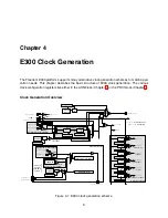
Figure 4.2 shows how the PLL output frequency is set using a combination of three read-write
fields:
pllr[2:0]
,
pllf[2:0]
,
pllq[1:0]
. The frequency constraints must be observed between
each stage for correct operation.
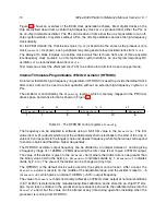
The
pllr[1:0]
field encodes the reference clock divide ratio as a 2-bit binary value, where the
value is one less than the divide ratio (i.e.,
00
=1,
11
=4). The frequency of the output of the
Summary of Contents for E300
Page 1: ...SiFive E300 Platform Reference Manual Version 1 0 1 c SiFive Inc ...
Page 2: ...2 SiFive E300 Platform Reference Manual Version 1 0 1 ...
Page 4: ...ii SiFive E300 Platform Reference Manual Version 1 0 1 ...
Page 12: ...4 SiFive E300 Platform Reference Manual Version 1 0 1 ...
Page 14: ...6 SiFive E300 Platform Reference Manual Version 1 0 1 ...
Page 22: ...14 SiFive E300 Platform Reference Manual Version 1 0 1 ...
Page 32: ...24 SiFive E300 Platform Reference Manual Version 1 0 1 ...
Page 40: ...32 SiFive E300 Platform Reference Manual Version 1 0 1 ...
Page 56: ...48 SiFive E300 Platform Reference Manual Version 1 0 1 ...
Page 60: ...52 SiFive E300 Platform Reference Manual Version 1 0 1 ...

