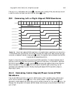
This technique provides symmetric PWM waveforms but only when the PWM cycle is at the
largest supported size. At a 16 MHz bus clock rate with 16-bit precision, this limits the fastest
PWM cycle to 244 Hz, or 62.5 kHz with 8-bit precision. Higher bus clock rates allow proportion-
ally faster PWM cycles using the single comparator center-aligned waveforms. This technique
also reduces the effective width resolution by a factor of 2.
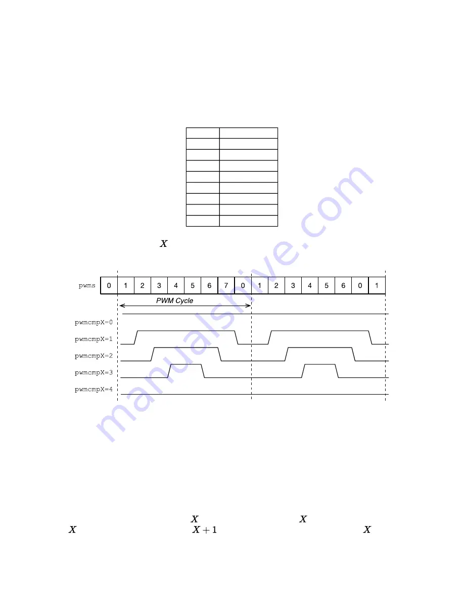
pwms
pwmscenter
000
000
001
001
010
010
011
011
100
011
101
010
110
001
111
000
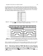
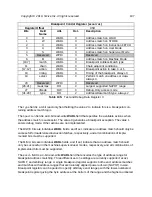
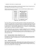
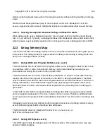
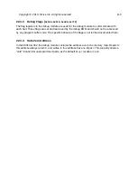
Figure 12:
Center-aligned PWM waveforms generated from one comparator. All possible
waveforms are shown for a 3-bit PWM precision. The signals can be inverted at the GPIOs to
generate opposite-phase waveforms.
When a comparator is operating in center mode, the deglitch circuit allows one 0-to-1 transition
during the first half of the cycle and one 1-to-0 transition during the second half of the cycle.
Generating Arbitrary PWM Waveforms using Ganging
A comparator can be ganged together with its next-highest-numbered neighbor to generate arbi-
trary PWM pulses. When the
pwmcmp
gang
bit is set, comparator
fires and raises its
pwm
gpio
signal. When comparator
(or
pwmcmp0
for
pwmcmp3
) fires, the
pwm
gpio
out-
put is reset to zero.
Table 97:
Illustration of how count value is inverted before presentation to comparator when
pwmcmp
center
is selected, using a 3-bit
pwms
value.
Copyright © 2019, SiFive Inc. All rights reserved.
101
Summary of Contents for FE310-G002
Page 1: ...SiFive FE310 G002 Manual v19p05 SiFive Inc ...
Page 11: ...Figure 1 FE310 G002 top level block diagram Copyright 2019 SiFive Inc All rights reserved 9 ...
Page 15: ...Chapter 2 List of Abbreviations and Terms 13 ...
Page 23: ...Chapter 4 Memory Map The memory map of the FE310 G002 is shown in Table 4 21 ...

