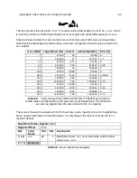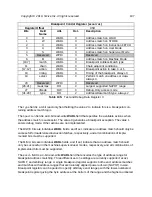
PWM Configuration Register (
pwmcfg
)
Register Offset
0x0
Bits
Field Name
Attr.
Rst.
Description
[3:0]
pwmscale
RW
X
PWM Counter scale
[7:4]
Reserved
8
pwmsticky
RW
X
PWM Sticky - disallow clearing
pwmcmp
ip
bits
9
pwmzerocmp
RW
X
PWM Zero - counter resets to zero after match
10
pwmdeglitch
RW
X
PWM Deglitch - latch
pwmcmp
ip
within same
cycle
11
Reserved
12
pwmenalways
RW
0x0
PWM enable always - run continuously
13
pwmenoneshot
RW
0x0
PWM enable one shot - run one cycle
[15:14]
Reserved
16
pwmcmp0center
RW
X
PWM0 Compare Center
17
pwmcmp1center
RW
X
PWM1 Compare Center
18
pwmcmp2center
RW
X
PWM2 Compare Center
19
pwmcmp3center
RW
X
PWM3 Compare Center
[23:20]
Reserved
24
pwmcmp0gang
RW
X
PWM0/PWM1 Compare Gang
25
pwmcmp1gang
RW
X
PWM1/PWM2 Compare Gang
26
pwmcmp2gang
RW
X
PWM2/PWM3 Compare Gang
27
pwmcmp3gang
RW
X
PWM3/PWM0 Compare Gang
28
pwmcmp0ip
RW
X
PWM0 Interrupt Pending
29
pwmcmp1ip
RW
X
PWM1 Interrupt Pending
30
pwmcmp2ip
RW
X
PWM2 Interrupt Pending
31
pwmcmp3ip
RW
X
PWM3 Interrupt Pending
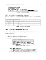
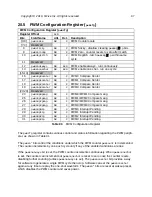
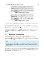
The
pwmcfg
register contains various control and status information regarding the PWM periph-
eral, as shown in Table 91.
The
pwmen*
bits control the conditions under which the PWM counter
pwmcount
is incremented.
The counter increments by one each cycle only if any of the enabled conditions are true.
If the
pwmenalways
bit is set, the PWM counter increments continuously. When
pwmenoneshot
is set, the counter can increment but
pwmenoneshot
is reset to zero once the counter resets,
disabling further counting (unless
pwmenalways
is set). The
pwmenoneshot
bit provides a way
for software to generate a single PWM cycle then stop. Software can set the
pwmenoneshot
again at any time to replay the one-shot waveform. The
pwmen*
bits are reset at wakeup reset,
which disables the PWM counter and saves power.
Table 91:
PWM Configuration Register
Copyright © 2019, SiFive Inc. All rights reserved.
97
Summary of Contents for FE310-G002
Page 1: ...SiFive FE310 G002 Manual v19p05 SiFive Inc ...
Page 11: ...Figure 1 FE310 G002 top level block diagram Copyright 2019 SiFive Inc All rights reserved 9 ...
Page 15: ...Chapter 2 List of Abbreviations and Terms 13 ...
Page 23: ...Chapter 4 Memory Map The memory map of the FE310 G002 is shown in Table 4 21 ...

