background image

20

Command List

................................................................................................................................................................................................................................

1) VISCA is a protocol which controls consumer camcorders developed by Sony. “VISCA” is a trademark of Sony Corporation.

Command List

VISCA

1)

/RS-232C

Commands

This Manual outlines an RS-232C control protocol and
command list for certain Sony cameras from which
control software can be developed.
THIS CONTROL PROTOCOL AND COMMAND
LIST IS PROVIDED BY SONY ON AN “AS-IS
BASIS” WITHOUT WARRANTY OF ANY KIND.
SONY DOES NOT WARRANT ANY PARTICULAR
RESULT FROM THE USE OF THIS CONTROL
PROTOCOL AND COMMAND LIST AND
DISCLAIMS AND EXCLUDES ALL
WARRANTIES, EXPRESS OR IMPLIED, WITH
RESPECT TO THAT CONTROL PROTOCOL AND
COMMAND LIST, INCLUDING, BUT NOT
LIMITED TO, ANY OR ALL IMPLIED
WARRANTIES OF MERCHANTABILITY OR
FITNESS FOR A PARTICULAR PURPOSE. IN
FACT, SONY SPECIFICALLY ACKNOWLEDGES
THAT SOFTWARE DEVELOPED BASED ON THIS
CONTROL PROTOCOL AND COMMAND LIST
MAY CAUSE MALFUNCTION OR DAMAGE TO
HARDWARE AND SOFTWARE USED WITH IT
(INCLUDING SONY HARDWARE AND
SOFTWARE) AND SPECIFICALLY DISCLAIMS
ANY LIABILITY FOR ANY SUCH
MALFUNCTION OR DAMAGE. THIS CONTROL
PROTOCOL AND COMMAND LIST SHOULD BE
USED WITH CAUTION.

Overview of VISCA

In VISCA the device outputting commands, for
example, a computer, is called the controller. The
device receiving the commands, an FCB series camera
is called the peripheral device. In this case, an FCB
series camera, is itself one of the peripheral devices.
In VISCA, up to seven peripheral devices like the FCB
series camera can be connected to one controller using
communication conforming to the RS-232C standard.
The parameters of RS-232C are as follows:
• Communication speed: 9.6 kbps/19.2 kbps/

38.4 kbps

• Data bits : 8
• Start bit : 1
• Stop bit : 1/2
• Non parity

Peripheral devices are connected in a daisy chain. As
shown in the following figure, the actual internal
connection is a one-direction ring, so that messages
return to the controller via the peripheral devices. The
devices on the network are assigned addresses.
The address of the controller is fixed at 0. The
addresses of the peripheral devices are 1, 2, 3 ... in
order, starting from the one nearest the conttoller. The
address of the peripheral device is set by sending
address commands during the initialization of the
network.

Summary of Contents for FCB-IX11AP

Page 1: ... 2004 Sony Corporation Color Camera Module FCB IX11A IX11AP A C4E 100 11 1 Technical Manual ...

Page 2: ...clipse 11 Spectral Sensitivity Characteristics 11 Vibration Specifications 11 Key Switch Circuitry 12 Key Function Specifications 13 Initial Settings Custom Preset and Backup 15 Mode Condition 17 Command List 20 VISCA RS 232C Commands 20 FCB Series Camera Commands 26 Specifications 42 Precautions 45 ...

Page 3: ...ter controller Six memory locations are provided to temporarily save and recall up to six sets of camera settings The EX view HAD CCD features 380 000 effective picture elements and shooting with enhanced sensitivity The minimum illumination required is 1 5 lux 1 60 s NTSC 1 50 s PAL With consideration given to environmental protection this module is designed to operate with low power consumption ...

Page 4: ...connector 3 WIDE button 4 TELE button Front Rear Bottom Top 5 CN701 connector 6 CN751 connector 7 Tripod screw holes When a tripod is used please use 5 5 mm 7 32 in screws to attach it to the camera Also please be sure to attach the tripod securely Left side 1 2 3 4 5 6 7 ...

Page 5: ...pplication software when the power is on Address set VISCA is a protocol which normally can support a daisy chain of up to seven attached devices Whenever a camera is connected for the first time be sure to use the address set to confirm the address ID Write Sets the camera ID Mute Blanks the screen and sends out a synchronizing signal Lens Initialization Initializes the zoom and focus of the lens...

Page 6: ...on to maximize the high frequency content of the picture in a center measurement area taking into consideration the high luminance and strong contrast components Normal AF Mode This is the normal mode for AF operations Interval AF Mode The mode used for AF movements carried out at defined intervals The time intervals for AF movements and for the timing of the stops can be set in one second increme...

Page 7: ...ow shutter 6 steps Iris Priority Variable Iris F1 8 to Close 18 steps Auto Gain and Shutter speed Manual Variable Shutter Iris and Gain Bright Variable Iris and Gain Close to F1 8 17 steps at 0 dB F1 8 15 steps from 0 to 28 dB AE Shutter Priority The shutter speed can be set freely by the user to a total of 22 steps 16 high speeds and 6 low speeds When the slow shutter is set the speed can be 1 30...

Page 8: ...4 0 dB 14 F1 8 6 dB 04 F16 0 dB 13 F1 8 4 dB 03 F19 0 dB 12 F1 8 2 dB 02 F22 0 dB 11 F1 8 0 dB 01 F28 0 dB 10 F2 0 0 dB 00 CLOSE 0 dB When switching from the Shutter Priority mode to the Bright mode the shutter speed set in the Shutter Priority mode is maintained Spot Exposure Mode In Full Auto AE the level for the entire screen is computed and the optimum Auto Iris and Gain levels are determined ...

Page 9: ...appear clearer Slow Shutter Auto Manual When the Slow Shutter is set to Auto this ensures that the slow shutter is engaged automatically when the brightness drops This occurs only when the AE mode is set to Full Auto Slow Shutter Manual is the factory setting Camera ID The ID can be set up to 65 536 0000 to FFFF As this will be memorized in the nonvolatile memory inside the camera data will be sav...

Page 10: ...ting items refer to the Initial Settings Custom Preset and Backup section on page 15 Title Display The camera can be given a title containing up to 20 characters such as ENTRANCE or LOBBY The position of the first character horizontal vertical of the title blinking state and color can also be changed Date and Time Display The date and time accuracy 30 s month can be displayed on the video monitor ...

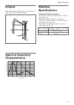
Page 11: ...minutes in each direction The camera vibration specification is to have no malfunction after this test Power spectrum density Effective overall value Test time 5 to 50 Hz 4 14 m2 s3 0 043 G2 Hz 50 to 100 Hz 36 dB oct 14 3 m s2 1 46 G 20 minutes 3 0 9 7 8 92 Eclipse When designing the housing refer to the dimensional allowance as shown in the figure below 9 56 2 1 8 2 1 Ye Cy G Mg 0 9 0 8 0 7 0 6 0...

Page 12: ... R122 2200 S107 S118 R110 1200 S126 R118 1500 S136 R127 2200 UP S153 R143 3900 DOWN S155 R146 8200 EXEC S156 R148 27k S142 R134 3900 S104 AE AUTO BRIGHT SHUTTER IRIS BACK LIGHT S115 R108 1200 S124 R116 1500 S133 R125 2200 S140 R132 3900 AUTO SLOW SHUTTER S150 R142 8200 S105 AUTO WB ONE PUSH WB ATW INDOOR OUTDOOR S116 R109 1200 S127 R117 1500 S134 R126 2200 S141 R133 3900 MANUAL WB APERTURE UP APER...

Page 13: ...ressed once and enable B control when pressed 2nd time Switchable with UP DOWN key Button operation Pressing repeatedly allowed Pressing repeatedly allowed Pressing repeatedly allowed Pressing repeatedly allowed Switch on off Pressing repeatedly allowed Pressing repeatedly allowed Switch between 1 and MAX magnification Switch between Auto and Manual Pressing repeatedly allowed Pressing repeatedly ...

Page 14: ...ally depending on the conditions Lower brightness setting Bright DOWN When not in Bright mode switching to Bright mode is made automatically depending on the conditions Button operation Switch on off Switch on off Switch on off Switch on off Switch on off Request setting t Setting is started with Exec Pressing Up Down key repeatedly allowed Switch date display time display off selection Switch on ...

Page 15: ...eset backup Zoom Position Wide end a a D Zoom On Off On a a D Zoom Separate Combine Combine a a D Zoom Position 00h a a Focus Position a a Focus Auto Manual Auto a a Near Limit Setting 8000h 40cm a a AF Sensitivity Normal a a AF Mode Normal a a AF Run Time 5 sec a a AF Interval 5 sec a a WB Mode Auto a a WB Data Rgain Bgain a a One Push WB Data a a AE Mode Full Auto a a Slow Shutter Mode Manual a ...

Page 16: ...on Initial settings Custom Standby preset backup Title Display On Off Off a a Title Setting a a Key Lock On Off Off a a Camera ID 0000h a a Note The number of times data can be written to EEPROM by executing Custom Preset is limited ...

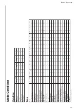
Page 17: ...Direct a a a a a Focus Far Near Stop a a Focus Direct a a a Focus Auto Manual a a a One Push AF a a Focus Infinity a a a Focus Near Limit a a a AF Sensitivity Normal Low a a a a a AF Mode Norm Interval Zoom a a a a a AF Activation Time Interval Setting a a a a a Camera Memory Set Reset a a a Camera Memory Recall a a a a Lens Initialization a a a Comp Scan a a a during recalling from key Mode Power...

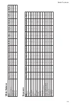
Page 18: ...reeze On MemRecall AE Full Auto AE Manual ShutterPriority Iris Priority Bright AE Full Auto a a a a a a AE Manual a a a a a a Shutter Priority a a a a a a Iris Priority a a a a a a Bright a a a a Shutter Setting a a a Iris Setting a a a Gain Setting a a Bright Setting a a Slow Shutter Auto Manual a a a a a a Exposure Compensation On Off a a a a a a Exposure Compensation Setting a a a a a a Backlig...

Page 19: ...e Power Off Initializing Power On Freeze On MemRecall Aperture Setting a LR_Reverse On Off a Freeze On Off a a Picture Effect Setting a Display On Off a a a Mute On Off a a a Title Setting a a a Key Lock On Off a a a ID Write a a a ...

Page 20: ...LIABILITY FOR ANY SUCH MALFUNCTION OR DAMAGE THIS CONTROL PROTOCOL AND COMMAND LIST SHOULD BE USED WITH CAUTION Overview of VISCA In VISCA the device outputting commands for example a computer is called the controller The device receiving the commands an FCB series camera is called the peripheral device In this case an FCB series camera is itself one of the peripheral devices In VISCA up to seven ...

Page 21: ...ra assigned address 1 from the controller address 0 is hexadecimal 81H The packet sent to the FCB series camera assigned address 2 is 82H In the command list as the header is 8X input the address of the FCB series camera at X The header of the reply packet from the FCB series camera assigned address 1 is 90H The packet from the FCB series camera assigned address 2 is A0H Some of the commands for s...

Page 22: ...d cancelled X0 6Y 05 FF No socket to be cancelled X0 6Y 41 FF Command not executable X 9 to F FCB series camera address 8 Y socket number Socket Number When command messages are sent to the FCB series camera it is normal to send the next command message after waiting for the completion message or error message to return However to deal with advanced uses the FCB series camera has two buffers memor...

Page 23: ...FF X 9 to F FCB series camera address 8 VISCA Interface Command IF_Clear Clears the command buffers in the FCB series camera and cancels the command currently being executed Command Packet Reply Packet Note IF_Clear 8X 01 00 01FF X0 50 FF IF_Clear broadcast 88 01 00 01 FF 88 01 00 01 FF X 1 to 7 FCB series camera address For inquiry packet X 9 to F FCB series camera address 8 For reply packet VISC...

Page 24: ...0 6y 04 FF Command Canceled z0 6y 05 FF No Socket Comments Returns ACK when a command has been accepted and Completion when a command has been executed Accepted a command which is not supported or a command lacking parameters There are two commands currently being executed and the command could not be accepted Could not execute the command in the current mode ACK is not returned for the inquiry co...

Page 25: ... illegal command parameters is accepted Indicates that two sockets are already being used executing two commands and the command could not be accepted when received Returned when a command which is being executed in a socket specified by the cancel command is canceled The completion message for the command is not returned Returned when no command is executed in a socket specified by the cancel com...

Page 26: ...n Switchover Direct 8x 01 04 46 00 00 0p 0q FF pq D Zoom Position CAM_Focus Stop 8x 01 04 08 00 FF Far Standard 8x 01 04 08 02 FF Near Standard 8x 01 04 08 03 FF Far Variable 8x 01 04 08 2p FF p 0 Low to 7 High Near Variable 8x 01 04 08 3p FF Direct 8x 01 04 48 0p 0q 0r 0s FF pqrs Focus Position Auto Focus 8x 01 04 38 02 FF AF ON OFF Manual Focus 8x 01 04 38 03 FF Auto Manual 8x 01 04 38 10 FF One...

Page 27: ... FF Bright Mode Manual control CAM_SlowShutter Auto 8x 01 04 5A 02 FF Auto Slow Shutter ON OFF Manual 8x 01 04 5A 03 FF CAM_Shutter Reset 8x 01 04 0A 00 FF Shutter Setting Up 8x 01 04 0A 02 FF Down 8x 01 04 0A 03 FF Direct 8x 01 04 4A 00 00 0p 0q FF pq Shutter Position CAM_Iris Reset 8x 01 04 0B 00 FF Iris Setting Up 8x 01 04 0B 02 FF Down 8x 01 04 0B 03 FF Direct 8x 01 04 4B 00 00 0p 0q FF pq Iri...

Page 28: ..._Date TimeSet Date TimeSet 8x 01 04 70 0m 0n 0p 0q 0r 0s mn Year 20mn 0t 0u 0v 0w FF pq Month rs Day 8x 01 07 29 0m 0n 0p 0q 0r 0s tu Hour vw Minute 0t 0u 0v 0w FF CAM_DateDisplay On 8x 01 04 71 02 FF Date display ON OFF 8x 01 07 2A 02 FF Off 8x 01 04 71 03 FF 8x 01 07 2A 03 FF CAM_TimeDisplay On 8x 01 04 72 02 FF Time display ON OFF 8x 01 07 2B 02 FF Off 8x 01 04 72 03 FF 8x 01 07 2B 03 FF CAM_Ti...

Page 29: ... rs Interval CAM_WBModeInq 8x 09 04 35 FF y0 50 00 FF Auto y0 50 01 FF In Door y0 50 02 FF Out Door y0 50 03 FF One Push WB y0 50 04 FF ATW y0 50 05 FF Manual CAM_RGainInq 8x 09 04 43 FF y0 50 00 00 0p 0q FF pq R Gain CAM_BGainInq 8x 09 04 44 FF y0 50 00 00 0p 0q FF pq B Gain CAM_AEModeInq 8x 09 04 39 FF y0 50 00 FF Full Auto y0 50 03 FF Manual y0 50 0A FF Shutter Priority y0 50 0B FF Iris Priorit...

Page 30: ...nq 8x 09 04 63 FF y0 50 00 FF Off y0 50 02 FF Neg Art y0 50 04 FF B W CAM_MemoryInq 8x 09 04 3F FF y0 50 pp FF pp Last Recall Memory No CAM_DisplayModeInq 8x 09 04 15 FF y0 50 02 FF On 8x 09 06 06 FF y0 50 03 FF Off CAM_TitleDisplayModeInq 8x 09 04 74 FF y0 50 02 FF On y0 50 03 FF Off CAM_MuteModeInq 8x 09 04 75 FF y0 50 02 FF On y0 50 03 FF Off CAM_KeyLockInq 8x 09 04 17 FF y0 50 00 FF Off y0 50 ...

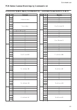
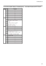
Page 31: ...sition LH 1 0 7 0 6 0 5 0 5 4 0 3 2 Zoom Position LL 1 0 7 0 6 0 5 0 6 4 0 3 2 Focus Near Limit H 1 0 7 0 6 0 5 0 7 4 0 3 2 Focus Near Limit L 1 0 7 0 6 0 5 0 8 4 0 3 2 Focus Position HH 1 0 7 0 6 0 5 0 9 4 0 3 2 Focus Position HL 1 0 7 0 6 0 5 0 10 4 0 3 2 Focus Position LH 1 0 7 0 6 0 5 0 11 4 0 3 2 Focus Position LL 1 0 FCB Series Camera Block Inquiry Command List Lens Control System Inquiry Co...

Page 32: ...ow 1 Digital Zoom 1 On 0 Off 0 Focus Mode 1 Auto 0 Manual 7 0 6 0 5 0 14 4 0 3 Low Contrast Detection 1 Yes 0 No 2 Camera Memory Recall 1 Executing 0 Stopped 1 Focus Command 1 Executing 0 Stopped 0 Zoom Command 1 Executing 0 Stopped 7 1 Terminator FFh 6 1 5 1 15 4 1 3 1 2 1 1 1 0 1 Byte Bit Comments Lens Control System Inquiry Commands 2 2 Command Packet 8x 09 7E 7E 00 FF ...

Page 33: ... 0 7 0 6 0 5 0 5 4 0 3 2 B Gain L 1 0 Byte Bit Comments 7 0 6 0 5 0 6 4 0 3 0 2 1 WB Mode 0 7 0 6 0 5 0 7 4 0 3 2 Aperture Gain 1 0 7 0 6 0 5 0 8 4 3 2 Exposure Mode 1 0 7 0 6 0 5 0 9 4 0 3 Spot AE 1 On 0 Off 2 Back Light 1 On 0 Off 1 Exposure Comp 1 On 0 Off 0 Slow Shutter 1 Auto 0 Manual 7 0 6 0 5 0 10 4 3 2 Shutter Position 1 0 7 0 6 0 5 0 11 4 3 2 Iris Position 1 0 Camera Control System Inquir...

Page 34: ...osition 1 0 7 0 6 0 5 0 13 4 3 2 Bright Position 1 0 7 0 6 0 5 0 14 4 0 3 2 Exposure Comp Position 1 0 7 1 Terminator FFh 6 1 5 1 15 4 1 3 1 2 1 1 1 0 1 Byte Bit Comments Camera Control System Inquiry Commands 2 2 Command Packet 8x 09 7E 7E 01 FF ...

Page 35: ...rse 1 On 0 Off 1 0 0 0 7 0 6 0 5 0 4 4 Mute 1 On 0 Off 3 Title Display 1 On 0 Off 2 Display 1 On 0 Off 1 0 0 0 7 0 6 0 5 0 5 4 0 3 2 Picture Effect Mode 1 0 7 0 6 0 5 0 6 4 0 3 0 2 0 1 0 0 0 7 0 6 0 5 0 7 4 0 3 0 2 0 1 0 0 0 7 0 6 0 5 0 8 4 0 3 2 Camera ID HH 1 0 7 0 6 0 5 0 9 4 0 3 2 Camera ID HL 1 0 7 0 6 0 5 0 10 4 0 3 2 Camera ID LH 1 0 7 0 6 0 5 0 11 4 0 3 2 Camera ID LL 1 0 Byte Bit Comments...

Page 36: ...ided 0 Not provided 3 Clock 1 Provided 0 Not provided 2 0 1 0 0 System 1 PAL 0 NTSC 7 0 6 0 5 0 13 4 0 3 2 V Phase H 1 0 7 0 6 0 5 0 14 4 0 3 2 V Phase L 1 0 7 1 Terminator FFh 6 1 5 1 15 4 1 3 1 2 1 1 1 0 1 Byte Bit Comments Other Inquiry Commands 2 2 Command Packet 8x 09 7E 7E 02 FF ...

Page 37: ... Digital Zoom Position H 1 0 7 0 6 0 5 0 3 4 0 3 2 Digital Zoom Position L 1 0 7 0 6 0 5 0 4 4 0 3 2 AF Activation Time H 1 0 7 0 6 0 5 0 5 4 0 3 2 AF Activation Time L 1 0 Byte Bit Comments 7 0 6 0 5 0 6 4 0 3 2 AF Interval Time H 1 0 7 0 6 0 5 0 7 4 0 3 2 AF Interval Time L 1 0 7 0 6 0 5 0 8 4 0 3 2 SpotAE Position X 1 0 7 0 6 0 5 0 9 4 0 3 2 SpotAE Position Y 1 0 7 0 6 0 5 0 10 4 0 3 0 2 0 1 0 ...

Page 38: ...unction Query Command 2 2 Command Packet 8x 09 7E 7E 03 FF Byte Bit Comments 7 0 6 0 5 0 12 4 0 3 0 2 0 1 0 0 0 7 0 6 0 5 0 13 4 0 3 0 2 0 1 0 0 0 7 0 6 0 5 0 14 4 0 3 0 2 0 1 0 0 0 7 1 Terminator FFh 6 1 5 1 15 4 1 3 1 2 1 1 1 0 1 ...

Page 39: ...5 0C 350 300 0B 250 215 0A 180 150 09 125 120 08 100 100 07 90 75 06 60 50 05 30 25 04 15 12 03 8 6 02 4 3 01 2 2 00 1 1 Iris 11 F1 8 10 F2 0 0F F2 4 0E F2 8 0D F3 4 0C F4 0 0B F4 8 0A F5 6 09 F6 8 08 F8 0 07 F9 6 06 F11 05 F14 04 F16 03 F19 02 F22 01 F28 00 CLOSE Gain 0F 28 dB 0E 26 dB 0D 24 dB 0C 22 dB 0B 20 dB 0A 18 dB 09 16 dB 08 14 dB 07 12 dB 06 10 dB 05 8 dB 04 6 dB 03 4 dB 02 2 dB 01 0 00 ...

Page 40: ...ht 1F F1 8 28 dB 1E F1 8 26 dB 1D F1 8 24 dB 1C F1 8 22 dB 1B F1 8 20 dB 1A F1 8 18 dB 19 F1 8 16 dB 18 F1 8 14 dB 17 F1 8 12 dB 16 F1 8 10 dB 15 F1 8 8 dB 14 F1 8 6 dB 13 F1 8 4 dB 12 F1 8 2 dB 11 F1 8 0 10 F2 0 0 0F F2 4 0 0E F2 8 0 0D F3 4 0 0C F4 0 0 0B F4 8 0 0A F5 6 0 09 F6 8 0 08 F8 0 0 07 F9 6 0 06 F11 0 05 F14 0 04 F16 0 03 F19 0 02 F22 0 01 F28 0 00 CLOSE 0 Exposure Comp 0E 7 10 5 dB 0D ...

Page 41: ...ill differ due to temperature Focus Near Limit 6000 1 m characteristics etc use as 7000 80 cm approximate values 8000 29 cm The lower 1 byte is fixed at 9000 10 cm 00 A000 4 7 cm B000 2 3 cm C000 1 0 cm R B gain 00 FF Aperture 00 0F 00 01 02 03 04 05 06 07 A B C D E F G H 08 09 0a 0b 0c 0d 0e 0f I J K L M N O P 10 11 12 13 14 15 16 17 Q R S T U V W X 18 19 1a 1b 1c 1d 1e 1f Y Z 1 2 20 21 22 23 24 ...

Page 42: ... 1 3 s PAL Recommended illumination 100 to 100 000 lux S N ratio 50 dB or more Back light compensation ON OFF Electronic shutter speed 1 1 to 1 10 000 s 22 steps White balance AUTO ATW Indoor Outdoor One Push WB Manual WB Gain Auto Manual 3 to 28 dB 2 dB steps Aperture control 16 steps Focus Auto H L On Push AF Manual Infinity Interval AF Zoom Trigger AF Preset 6 positions Serial interface VISCA p...

Page 43: ...8 15 16 21 27 32 0 5 1 32 4 3 16 14 0 1 9 16 20 0 1 13 16 8 11 32 65 2 5 8 40 3 1 5 8 Tripod screw Depth 5 5 mm 7 32 in or less 20 8 27 32 18 5 3 4 19 3 25 32 7 4 5 16 11 4 15 32 15 8 5 8 1 4 20UNC 5 7 32 15 3 5 8 18 0 1 23 32 4 M2 Depth 4 mm 3 16 in or less Label model number M 3D P0 75 Depth 3 m m 1 8 in or less ...

Page 44: ...n No Name Level 1 DC IN 6V to 12V 2 GND for DC IN 3 NC 4 VBS OUT Composite video signal 5 GND For VBS OUT 6 Y Out 7 GND For Y 8 C Out 9 GND For C CN751 for communications Pin No Name Level 1 GND 2 GND 3 KEY_AD0 4 KEY_AD1 5 KEY_AD2 6 KEY_AD3 7 KEY_AD4 8 KEY_AD5 9 KEY_AD6 10 KEY_AD7 11 NC 12 Strobe Connector type Molex 52689 1240 FFC 0 5 mm CN701 for FFC cable Strobe signal specifications Vertical t...

Page 45: ...ot use or store the camera in the following extreme conditions Extremely hot or cold places operating temperature 0 C to 40 C 32 F to 104 F Close to generators of powerful electromagnetic radiation such as radio or TV transmitters Where it is subject to fluorescent light reflections Where it is subject to unstable flickering etc lighting conditions Where it is subject to strong vibration Care of t...

Reviews: