Printed in the Federal Republic of Germany
TR-Electronic GmbH 2018, All Rights Reserved
11/12/2019
TR - ELA - BA - DGB - 0027 - 03
Page 155 of 167
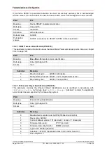
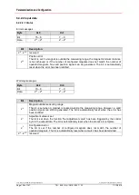
Life cycle counter
Byte
X+4
Bit
7 – 0
Data
2
7
– 2
0
Bit
Description
2
0
…2
7
Life cycle counter
The measuring system increments the 8-bit counter in each transfer cycle. Valid values
are 1 to 255. If the value is 0 or if it remains unchanged, a general error is present.
Number of configured magnets
Byte
X+5
Bit
7 – 0
Data
2
7
– 2
0
Bit
Description
2
0
…2
7
Number of configured magnets
Feedback from configured magnets, binary-coded.
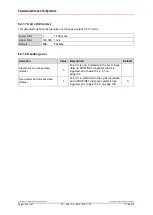
6.4.2.2.2 Position and speed values 1 to 30
Position value, Magnet 1 (Integer32)
Byte
X+6
X+7
X+8
X+9
Bit
31 – 24
23 – 16
15 – 8
7 – 0
Data
2
31
– 2
24
2
23
– 2
16
2
15
– 2
8
2
7
– 2
0
The position is output as a signed two's complement value.
Speed value, Magnet 1 (Integer16)
Byte
X+10
X+11
Bit
15 – 8
7 – 0
Data
2
15
– 2
8
2
7
– 2
0
The speed is output as a two's complement value with preceding sign.
This is followed by the position and speed values of magnets 2 to 30.


