Parameterization and Configuration
TR-Electronic GmbH 2018, All Rights Reserved
Printed in the Federal Republic of Germany
Page 156 of 167
TR - ELA - BA - DGB - 0027 - 03
11/12/2019
6.4.2.3 Output data
6.4.2.3.1 Control byte, preset adjustment
Danger of physical injury and damage to property due to an actual value
jump during execution of the preset adjustment function!
•
The preset adjustment function should only be executed when the
measuring system is stationary, or the resulting actual value jump must be
permitted by both the program and the application!
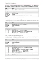
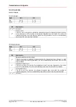
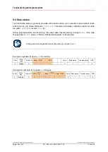
Control byte, preset adjustment
Byte
X+0
Bit
7 – 0
Data
2
7
– 2
0
Bit
Description
2
0
Set adjustment value
The measuring system can be adjusted to any position value with this function. The
written adjustment value relates to the addressed magnet or magnets.
The adjustment function is controlled via bits 2
0
Set adjustment value
and 2
2
Adjustment absolute/relative
and via bit 2
1
Adjustment value is set
in
the warning messages of the status display (chapter 6.4.2.2.1 on page 154)
2
1
Save adjustment value
To permanently store the newly set position value (voltage OFF/ON), the internally
calculated offset value must be saved by setting this bit.
2
2
Adjustment absolute/relative
Adjustment mode = absolute, prevailing adjustment value e.g. = 0:
Set bit 2
0
and 2
2
to 0. The current position value is set to the value 0 with a rising edge 0
->1 of bit 2
0
.
The adjustment execution is acknowledged in the warning messages by setting bit 2
1
. In
order to complete the adjustment execution, bit 2
0
must be reset again. Bit 2
1
is then also
automatically reset in the warning messages.
The internally calculated offset value must be permanently stored via bit 2
1
.
Adjustment mode = relative, prevailing adjustment value e.g. = 1000, current
position e.g. = 4000:
Set bit 2
2
to 1 and bit 2
0
to 0. The current position value 4000 is set to the value 5000
with a rising edge 0 ->1 of bit 2
0
.
The process then continues as described above.
2
3
…2
7
reserved

