33
4.5 Description of the commands
To see the standard values and the full list of the commands available at user level see the Factory Acceptance Test report ( * :
enabled command).
The reception signal parameters determine for the most part the Metal Detector’s detection capability (just consider the
sensitivity adjustment). If any variation is to be implemented, it must be checked for compatibility with security specifications.
4.5.1
Summary of the parameters according to their function
Installation parameters ............................... CH, IS, LD, NP, OTS, PE
Detection capability parameters ................ LD, LC, SE, SENT
Audio alarm indication parameters............ AD, AT, AV, MV
Visual alarm indication parameters ........... AD, MTI
Zone alarm indication parameters ............. LBI, ZL
Random alarm parameters ......................... AP, RAT, RAV
Statistics parameters .................................. AC, CR
Access to controls parameters .................. NP, UP
Communications parameters ..................... BTE, NETV, WIE
Service & Troubleshooting parameters .... AVS, EN, EVA, SC, CH, OTS
Periodic performance test parameters ...... OFV
Information parameters ............................... WHO, HE, PT
4.5.2
Description of the commands
T
(
Type)
:
C= command R= status request
NOTE
Functions available in remote mode only.
All functions are available both in local mode and in remote mode, with the
exception of commands HE, PE, PT, WHO which can be executed in remote mode only.
Code
Meaning
Range
T Description
AC
Number of
alarms
detected
0-9999999
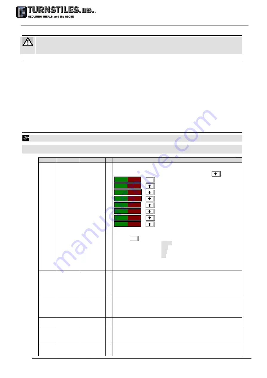
R Equipment fitted with photocells only. Only inbound transits
Number of alarms detected
In local programming the values are scrolled by pressing the UP arrow key
.
-
AC
-
*__*
ENTER
P
_
10000
number of passages through the antenna
TA
_-
2350
the total number of passages with alarm
TR
_
23.5%
the alarms/passages ratio as a percentage
MA
_-
1500
number of passages with alarm due to a metal mass
MR
_
15.0%
metal alarms/passages ratio
RA
_-
1000
number of passages with random alarm
RR
_
10.0%
random alarms/passages ratio
Example of remote-mode display, setting AP= 10 (10%):
AC
ENTER
TOTAL
METAL
RANDOM
P
10000 10000 10000
number of passages
A 2350 1500 1000
number of alarms
R.R 23.5 15.0 10.0
percentages
NOTE: MA, MR, RA, RR and RANDOM column are not provided if AP=0.
See also: AP, CR.
AD
Alarm duration 0-5
C,
R
It selects the alarm duration, in seconds, using two different ranges.
in this case the display provides the same indications as for Proportional Alarm Indication:
0
reset time = 0.3s
1 , 2, 3, 4 and 5
reset time = 1s, 2s, 3s, 4s and 5s
AP
Probability of
random alarm
for inbound
transits
0-100 (%)
C
R
Equipment fitted with photocells only.
Selects the probability of random alarms (in percentage), for transits along the inbound
direction (defined by the GD parameter).
See also GD parameter.
AT
Metal Mass
Alarm tone
0-44
C
R
This parameter sets the tone of the metal alarm sound.
During local programming, the device provides an audible signal using the selected tone.
AV
Metal Mass
Alarm volume
0-9
C
R
This parameter sets the volume of the alarm sound:
0 (disconnected alarm)
9 (maximum volume).
During local programming, the device provides an audible signal using the selected sound.
AVS
Anti-vibration
System
NO, YES
C
R
It enables/disables the embedded Anti-Vibration System. This system compensates the
environmental mechanical vibrations acquired using the EVA command (see below) .
303-670-1099


