background image

Yokogawa DX Serial Driver

default timeout for most serial drivers is based on a baud rate of 9600 baud or better. When using a driver
at lower baud rates, increase the timeout to compensate for the increased time required to acquire data.

Attempts Before Timeout

:  This property specifies how many times the driver issues a communications

request before considering the request to have failed and the device to be in error. The valid range is 1 to
10. The default is typically 3, but can vary depending on the driver's specific nature. The number of attempts
configured for an application depends largely on the communications environment. This property applies to
both connection attempts and request attempts.

Timing

Inter-Request Delay

:  This property specifies how long the driver waits before sending the next request to

the target device. It overrides the normal polling frequency of tags associated with the device, as well as
one-time reads and writes. This delay can be useful when dealing with devices with slow turnaround times
and in cases where network load is a concern. Configuring a delay for a device affects communications with
all other devices on the channel. It is recommended that users separate any device that requires an inter-
request delay to a separate channel if possible. Other communications properties (such as communication
serialization) can extend this delay. The valid range is 0 to 300,000 milliseconds; however, some drivers may
limit the maximum value due to a function of their particular design. The default is 0, which indicates no
delay between requests with the target device.

Note

: Not all drivers support Inter-Request Delay. This setting does not appear if it is not available.

Device Properties — Auto-Demotion

The Auto-Demotion properties can temporarily place a device off-scan in the event that a device is not
responding. By placing a non-responsive device offline for a specific time period, the driver can continue to
optimize its communications with other devices on the same channel. After the time period has been
reached, the driver re-attempts to communicate with the non-responsive device. If the device is responsive,
the device is placed on-scan; otherwise, it restarts its off-scan time period.

Demote on Failure

: When enabled, the device is automatically taken off-scan until it is responding again.

Tip

: Determine when a device is off-scan by monitoring its demoted state using the _AutoDemoted

system tag.

Timeouts to Demote

: Specify how many successive cycles of request timeouts and retries occur before the

device is placed off-scan. The valid range is 1 to 30 successive failures. The default is 3.

Demotion Period

: Indicate how long the device should be placed off-scan when the timeouts value is

reached. During this period, no read requests are sent to the device and all data associated with the read
requests are set to bad quality. When this period expires, the driver places the device on-scan and allows for
another attempt at communications. The valid range is 100 to 3600000 milliseconds. The default is 10000
milliseconds.

Discard Requests when Demoted

: Select whether or not write requests should be attempted during the

off-scan period. Disable to always send write requests regardless of the demotion period. Enable to discard

www. ptc.com

14

Summary of Contents for DX Series

Page 1: ...Yokogawa DX Serial Driver 2018 PTC Inc All Rights Reserved ...

Page 2: ...eneration 15 Device Properties Device Configuration 17 Device Properties Redundancy 18 Data Types Description 19 Address Descriptions 20 DX102 Addressing 20 DX104 Addressing 22 DX106 Addressing 25 DX112 Addressing 28 DX204 Addressing 30 DX208 Addressing 33 DX210 Addressing 35 DX220 Addressing 38 DX230 Addressing 40 MV100 Addressing 43 MV200 Addressing 45 Error Descriptions 49 Address address is ou...

Page 3: ...name error mask 50 COMn does not exist 51 COMn is in use by another application 51 Error opening COMn 51 Unable to set comm parameters on COMn 51 Device device name is not responding 52 Unable to write to address on device device name 52 Index 53 www ptc com 3 ...

Page 4: ...erial device Automatic Tag Database Generation How can I easily configure tags for the Yokogawa DX Serial Driver Error Descriptions What error messages does the Yokogawa DX Serial Driver produce Overview The Yokogawa DX Serial Driver provides a reliable way to connect Yokogawa DX Serial devices to OPC client applications including HMI SCADA Historian MES ERP and countless custom applications It is...

Page 5: ... 232 select a Device ID of zero 0 This tells the driver to use the RS 232 mode for communications If intending to use either RS 422 or RS 485 communications select a Device ID for each station that is between 1 and 16 for RS 422 and between 1 and 31 for RS 485 When using RS 232 only configure one device on the channel Request Timeout This parameter specifies the amount of time that the driver will...

Page 6: ...ration these properties can be changed at any time This includes changing the channel name to prevent clients from registering data with the server If a client has already acquired an item from the server before the channel name is changed the items are unaffected If after the channel name has been changed the client application releases the item and attempts to re acquire using the old channel na...

Page 7: ...m Settings section l Ethernet Encap Select if Ethernet Encapsulation is used for communications which displays the Ethernet Settings section l Shared Verify the connection is correctly identified as sharing the current configuration with another channel This is a read only property Serial Port Settings COM ID Specify the Communications ID to be used when communicating with devices assigned to the ...

Page 8: ...ho suppression it is recommended that echoes be disabled or a RS 485 converter be used Operational Behavior l Report Comm Errors Enable or disable reporting of low level communications errors When enabled low level errors are posted to the Event Log as they occur When disabled these same errors are not posted even though normal request failures are The default is Enable l Close Idle Connection Cho...

Page 9: ...ing Fail provides the client with an update that indicates failure The default setting is Ignore Channel Properties Write Optimizations As with any server writing data to the device may be the application s most important aspect The server intends to ensure that the data written from the client application gets to the device on time Given this goal the server provides optimization properties that ...

Page 10: ...ations to perform reads are processed continuously This allows optimization for applications with continuous writes versus a more balanced back and forth data flow Note It is recommended that the application be characterized for compatibility with the write optimization enhancements before being used in a production environment Channel Properties Advanced This group is used to specify advanced cha...

Page 11: ...a Channel Device Tag and Tag Group in server help Description User defined information about this device Many of these properties including Description have an associated system tag Channel Assignment User defined name of the channel to which this device currently belongs Driver Selected protocol driver for this device This property specifies the driver selected during channel creation It is disab...

Page 12: ... Mode In this mode the driver does not attempt to communicate with the physical device but the server continues to return valid OPC data Simulated stops physical communications with the device but allows OPC data to be returned to the OPC client as valid data While in Simulation Mode the server treats all device data as reflective whatever is written to the simulated device is read back and each O...

Page 13: ...be provided when the new item reference shares the same address scan rate data type client access and scaling properties A device read is used for the initial update for the first client reference only The default is disabled any time a client activates a tag reference the server attempts to read the initial value from the device Device Properties Timing The device Timing properties allow the driv...

Page 14: ...ch indicates no delay between requests with the target device Note Not all drivers support Inter Request Delay This setting does not appear if it is not available Device Properties Auto Demotion The Auto Demotion properties can temporarily place a device off scan in the event that a device is not responding By placing a non responsive device offline for a specific time period the driver can contin...

Page 15: ... to build the server s tags 2 If an Ethernet I O system supports detection of its own available I O module types the communications driver automatically generates tags in the server that are based on the types of I O modules plugged into the Ethernet I O rack Note Automatic tag database generation s mode of operation is completely configurable For more information refer to the property description...

Page 16: ...ct as the prior option and also posts an error message to the server s Event Log when a tag overwrite would have occurred Note Removing OPC tags affects tags that have been automatically generated by the communications driver as well as any tags that have been added using names that match generated tags Users should avoid adding tags to the server using names that may match tags that are automatic...

Page 17: ... at communication startup that will start the math computation The default setting is unchecked Time Settings l Date and Time This property specifies the origin of the data value of the Date and Time data types which represent the date and time of the latest data Options include Device Time and System Time The default setting is Device Time Descriptions of the options are as follows l Device Time ...

Page 18: ...Number In this option the driver generates tag names based on an item s channel number For example CH01 or CH01_alarm1 l Device Tagname In this option the driver generates tag names using the tag name returned by the device for a channel Special characters such as slashes or pound signs are not allowed For example Flow or Flow_alarm1 Device Properties Redundancy Redundancy is available with the Me...

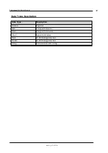
Page 19: ...ption Data Type Description Boolean Single bit Byte Unsigned 8 bit value Word Unsigned 16 bit value Short Signed 16 bit value Float 32 bit floating point value Double 64 bit floating point value String Null terminated ASCII string www ptc com 19 ...

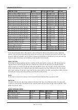
Page 20: ...d Byte Read Only Alarm Level2 Status of Channel CHxx Alarm2 01 02 Short Word Byte Read Only Alarm Level3 Status of Channel CHxx Alarm3 01 02 Short Word Byte Read Only Alarm Level4 Status of Channel CHxx Alarm4 01 02 Short Word Byte Read Only Set and Read Level1 Alarm Setpoint CHxx ASP1 01 02 Double Float Read Write Set and Read Level2 Alarm Setpoint CHxx ASP2 01 02 Double Float Read Write Set and ...

Page 21: ...esses are only read from the device at the start of a communications session Once read the values will not be refreshed until the server has been restarted or the Reset tag has been invoked To invoke a reset a non zero value must be written to the Reset tag Once the Reset tag has been invoked the driver will reinitialize all startup data from the device Alarm Setpoints Data values for Alarm Setpoi...

Page 22: ...rned by the device Control Math Execution The MathControl address type is only available for devices equipped with the math option otherwise write operations to the MathControl tag for non math equipped devices will return an error Control Command and Response The Command address allows the user to send a string command and receive a string response to and from the device This allows the user to s...

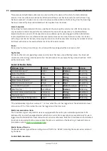
Page 23: ...hort Word Byte Read Only Highest Measuring Channel CH High Short Word Byte Read Only Math Channels Address Type Format Range Data Type Access Process Value of Math Channel CHxx or CHxx PV 31 34 Double Float Read Only Alarm Summary of Math Channel CHxx Alarm 31 34 Short Word Byte Read Only Alarm Level1 Status of Math Channel CHxx Alarm1 31 34 Short Word Byte Read Only Alarm Level2 Status of Math Ch...

Page 24: ...the channel number For example the tag name of address CH01 will be returned as CH01 General Device Data Address Type Format Range Data Type Access Administrator Level Admin Boolean Read Only Date of Last Data Date String Read Only Time of Last Data Time String Read Only Model Name of Device Model String Read Only Math Communication Data CDxx 01 04 Float Read Write Control Math Execution MathContr...

Page 25: ...pes and null string for string data types DX106 Addressing The driver supports the following addresses for this device The default data type for each address type is shown in bold Measured Channels Address Type Format Range Data Type Access Process Value of Channel CHxx or CHxx PV 01 06 Double Float Read Only Alarm Summary of Channel CHxx Alarm 01 06 Short Word Byte Read Only Alarm Level1 Status o...

Page 26: ... associated with these addresses are only read from the device at the start of a communications session Once read the values will not be refreshed until the server has been restarted or the Reset tag has been invoked To invoke a reset a non zero value must be written to the Reset tag Once the Reset tag has been invoked the driver will reinitialize all startup data from the device Alarm Setpoints D...

Page 27: ... address type will have a string value of DX100 or DX200 indicating the model series returned by the device Control Math Execution The MathControl address type is only available for devices equipped with the math option otherwise write operations to the MathControl tag for non math equipped devices will return an error Control Command and Response The Command address allows the user to send a stri...

Page 28: ...annel CHxx tag 01 12 String Read Only Status of Channel CHxx status 01 12 String Read Only Lowest Measuring Channel CH Low Short Word Byte Read Only Highest Measuring Channel CH High Short Word Byte Read Only Math Channels Address Type Format Range Data Type Access Process Value of Math Channel CHxx or CHxx PV 31 42 Double Float Read Only Alarm Summary of Math Channel CHxx Alarm 31 42 Short Word B...

Page 29: ...INF Tag Names For devices that do not support tag names and channels that have unspecified tag names the driver will construct an internal tag name based on the channel number For example the tag name of address CH01 will be returned as CH01 General Device Data Address Type Format Range Data Type Access Administrator Level Admin Boolean Read Only Date of Last Data Date String Read Only Time of Las...

Page 30: ...re unreadable for these addresses and the associated tags are not included in the scan list The current data value for these tags will always be 0 for numeric data types and null string for string data types DX204 Addressing The driver supports the following addresses for this device The default data type for each address type is shown in bold Measured Channels Address Type Format Range Data Type ...

Page 31: ...ead Only Status of Math Channel CHxx status 01 38 String Read Only Lowest Math Channel CHA Low Short Word Byte Read Only Highest Math Channel CHA High Short Word Byte Read Only Data associated with these addresses are only read from the device at the start of a communications session Once read the values will not be refreshed until the server has been restarted or the Reset tag has been invoked To...

Page 32: ...the Reset tag is invoked For more information refer to Note on Initialized Data Model Name of Device The Model address type will have a string value of DX100 or DX200 indicating the model series returned by the device Control Math Execution The MathControl address type is only available for devices equipped with the math option otherwise write operations to the MathControl tag for non math equippe...

Page 33: ...Only Lower Scale Value of Channel CHxx scale_Lo 01 08 Double Float Read Only Unit String of Channel CHxx unit 01 08 String Read Only Tagname of Channel CHxx tag 01 08 String Read Only Status of Channel CHxx status 01 08 String Read Only Lowest Measuring Channel CH Low Short Word Byte Read Only Highest Measuring Channel CH High Short Word Byte Read Only Math Channels Address Type Format Range Data ...

Page 34: ...rate of ASP items and or reducing the number of active ASP items will increase the read performance of the PV and alarm data Scales Data values for Scale_Hi and Scale_Lo for channels that are skipped will be returned as INF Tag Names For devices that do not support tag names and channels that have unspecified tag names the driver will construct an internal tag name based on the channel number For ...

Page 35: ...me that an address is not present in the device it will post an error message and remove the tag from its scan list 2 Addresses that have Write Only access are assigned a default access of Read Write However data values are unreadable for these addresses and the associated tags are not included in the scan list The current data value for these tags will always be 0 for numeric data types and null ...

Page 36: ...e Float Read Only Lower Scale Value of Math Channel CHxx scale_Lo 31 60 Double Float Read Only Unit String of Math Channel CHxx unit 01 60 String Read Only Tagname of Math Channel CHxx tag 01 60 String Read Only Status of Math Channel CHxx status 01 60 String Read Only Lowest Math Channel CHA Low Short Word Byte Read Only Highest Math Channel CHA High Short Word Byte Read Only Data associated with...

Page 37: ...re available only for users logged in at the Administrator level and will return an error otherwise Note that CD addresses are initialized read at startup and will not be reread unless the server is restarted or the Reset tag is invoked For more information refer to Note on Initialized Data Model Name of Device The Model address type will have a string value of DX100 or DX200 indicating the model ...

Page 38: ...P3 01 20 Double Float Read Write Set and Read Level4 Alarm Setpoint CHxx ASP4 01 20 Double Float Read Write Upper Scale Value of Channel CHxx scale_Hi 01 20 Double Float Read Only Lower Scale Value of Channel CHxx scale_Lo 01 20 Double Float Read Only Unit String of Channel CHxx unit 01 20 String Read Only Tagname of Channel CHxx tag 01 20 String Read Only Status of Channel CHxx status 01 20 Strin...

Page 39: ...sers logged in at the Administrator level and will return an error otherwise Alarm setpoint values are read one channel at a time For devices with a large number of channels increasing the scan rate of ASP items and or reducing the number of active ASP items will increase the read performance of the PV and alarm data Scales Data values for Scale_Hi and Scale_Lo for channels that are skipped will b...

Page 40: ...ddress should be performed with extreme care Notes 1 The actual number of addresses available for of each type depends on the configuration of the Yokogawa device If the driver finds at Runtime that an address is not present in the device it will post an error message and remove the tag from its scan list 2 Addresses that have Write Only access are assigned a default access of Read Write However d...

Page 41: ...ead Level4 Alarm Setpoint CHxx ASP4 31 60 Double Float Read Write Upper Scale Value of Math Channel CHxx scale_Hi 31 60 Double Float Read Only Lower Scale Value of Math Channel CHxx scale_Lo 31 60 Double Float Read Only Unit String of Math Channel CHxx unit 01 60 String Read Only Tagname of Math Channel CHxx tag 01 60 String Read Only Status of Math Channel CHxx status 01 60 String Read Only Lowes...

Page 42: ... CD address type is only valid for devices equipped with the math option and write operations to CD addresses for non math equipped devices will return an error Write operations are available only for users logged in at the Administrator level and will return an error otherwise Note that CD addresses are initialized read at startup and will not be reread unless the server is restarted or the Reset...

Page 43: ...Channel CHxx Alarm4 01 12 Short Word Byte Read Only Set and Read Level1 Alarm Setpoint CHxx ASP1 01 12 Double Float Read Write Set and Read Level2 Alarm Setpoint CHxx ASP2 01 12 Double Float Read Write Set and Read Level3 Alarm Setpoint CHxx ASP3 01 12 Double Float Read Write Set and Read Level4 Alarm Setpoint CHxx ASP4 01 12 Double Float Read Write Upper Scale Value of Channel CHxx scale_Hi 01 12...

Page 44: ...tartup data from the device Alarm Setpoints Data values for Alarm Setpoints that are undefined in the device will be returned as INF Data values can only be written to Alarm Setpoints that are defined in the device Write operations to undefined Alarm Setpoints will return an error Write operations are available only for users logged in at the Administrator level and will return an error otherwise ...

Page 45: ...ror Control Command and Response The Command address allows the user to send a string command and receive a string response to and from the device This allows the user to send any command to the device including commands not directly supported by the driver This tag is only available to users logged in at the Administrator level otherwise write operations will return an error Caution Write operati...

Page 46: ...CHxx PV 31 60 Double Float Read Only Alarm Summary of Math Channel CHxx Alarm 31 60 Short Word Byte Read Only Alarm Level1 Status of Math Channel CHxx Alarm1 31 60 Short Word Byte Read Only Alarm Level2 Status of Math Channel CHxx Alarm2 31 60 Short Word Byte Read Only Alarm Level3 Status of Math Channel CHxx Alarm3 31 60 Short Word Byte Read Only Alarm Level4 Status of Math Channel CHxx Alarm4 31...

Page 47: ...of Last Data Date String Read Only Time of Last Data Time String Read Only Model Name of Device Model String Read Only Math Communication Data CDxx 01 30 Float Read Write Control Math Execution MathControl Short Word Byte Write Only Reset Alarms AlarmReset Boolean Write Only Control Command and Response Command String Read Write Previous Screen PreScreen Boolean Write Only Direct Reloading of Conf...

Page 48: ...mand address should be performed with extreme care Notes 1 The actual number of addresses available for of each type depends on the configuration of the Yokogawa device If the driver finds at Runtime that an address is not present in the device it will post an error message and remove the tag from its scan list 2 Addresses that have Write Only access are assigned a default access of Read Write How...

Page 49: ... on COMn Device Status Messages Device device name is not responding Unable to write to address on device device name Address address is out of range for the specified device or register Error Type Warning Possible Cause A tag address that has been specified dynamically references a location that is beyond the range of supported locations for the device Solution Verify the address is correct if it...

Page 50: ...he access mode in the client application Missing address Error Type Warning Possible Cause A tag address that has been specified dynamically has no length Solution Re enter the address in the client application Communications error on channel name error mask Error Type Serious Error Mask Definitions B Hardware break detected F Framing error E I O error O Character buffer overrun R RX buffer overru...

Page 51: ...ing used by another application Solution 1 Verify that the correct port has been assigned to the channel 2 Verify that only one copy of the current project is running Error opening COMn Error Type Fatal Possible Cause The specified COM port could not be opened due to an internal hardware or software problem on the target computer Solution Verify that the COM port is functional and may be accessed ...

Page 52: ...the named device matches that of the actual device 3 Increase the Connect Timeout value in the Timeout page of Device Properties 4 Increase the Request Timeout setting so that the entire response can be handled Unable to write to address on device device name Error Type Serious Possible Cause 1 The connection between the device and the host PC is broken 2 The named device may have been assigned an...

Page 53: ... error mask 50 Communications Timeouts 13 14 COMn does not exist 51 COMn is in use by another application 51 Connect Timeout 13 Create 16 D Data Collection 12 Data Type type is not valid for device address address 49 Data Types Description 19 Delete 16 Demote on Failure 14 Demotion Period 14 Description 11 Device device name is not responding 52 Device address address contains a syntax error 49 De...

Page 54: ...1 DWord 19 DX102 Addressing 20 DX104 Addressing 22 DX106 Addressing 25 DX112 Addressing 28 DX204 Addressing 30 DX208 Addressing 33 DX210 Addressing 35 DX220 Addressing 38 DX230 Addressing 40 E Error Descriptions 49 Error opening COMn 51 F Float 19 G General 11 Generate 15 I ID 12 Initial Updates from Cache 13 Inter Request Delay 14 www ptc com 54 ...

Page 55: ... N Name 11 O On Device Startup 15 On Duplicate Tag 16 On Property Change 15 Overview 4 Overwrite 16 P Parent Group 16 R Redundancy 18 Request All Data at Scan Rate 13 Request Data No Faster than Scan Rate 13 Request Timeout 14 Respect Client Specified Scan Rate 13 Respect Tag Specified Scan Rate 13 www ptc com 55 ...

Page 56: ...al Driver S Scan Mode 12 Setup 5 Short 19 Simulated 12 T Tag Generation 15 Timeouts to Demote 14 U Unable to set comm parameters on COMn 51 Unable to write tag address on device device name 52 W Word 19 www ptc com 56 ...

Reviews: