background image

Regenerative DC Electronic

Load

IT8000 Series Programming Guide

Model: IT8000 Series

Version: V1.0/12,2019

Summary of Contents for IT8000 Series

Page 1: ...Regenerative DC Electronic Load IT8000 Series Programming Guide Model IT8000 Series Version V1 0 12 2019...

Page 2: ...ict with these terms the warranty terms in the separate agreement shall prevail Technology Licenses The hardware and or software de scribed herein are furnished under a li cense and may be used or cop...

Page 3: ...rvice must be shipped PRE PAID And ITECH will pay for return of the product to customer If the product is returned to ITECH for warranty service from overseas all the freights duties and other taxes s...

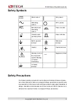
Page 4: ...g refer to this manual for specific Warning or Caution information Negative terminal A chassis terminal Safety Precautions The following safety precautions must be observed during all phases of opera...

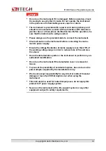
Page 5: ...cting the instru ment to power supply Ensure the voltage fluctuation of mains supply is less than 10 of the working voltage range in order to reduce risks of fire and elec tric shock Do not install al...

Page 6: ...uipment damage SHOCK HAZARD LETHAL VOLTAGES This product can input the dangerous voltage that can cause personal injury and the operator must always be protected from electric shock Ensure that the in...

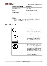
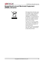
Page 7: ...visions of all rel evant European laws if the year is shown it indicates that the year when the design is approved This instrument complies with the WEEE directive 2002 96 EC tag re quirements This at...

Page 8: ...complies with tag re quirements of the WEEE directive 2002 96 EC This tag indicates that the electronic equipment cannot be disposed of as ordinary household waste Product Category According to the eq...

Page 9: ...1 IEC 61000 3 2 2018 RLV IEC 61000 3 3 2013 A1 2017 IEC 61000 4 2 2008 IEC 61000 4 3 2006 A1 2007 A2 2010 EN 61000 4 3 A1 2008 A2 2010 IEC 61000 4 4 2012 IEC 61000 4 5 2014 A1 2017 IEC 61000 4 6 2013...

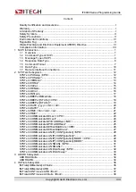
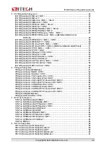
Page 10: ...IMMediate 18 SYSTem BEEPer STATe CPD 18 SYSTem BEEPer STATe 19 SYSTem DATE yyyy mm dd 20 SYSTem DATE 21 SYSTem TIME hh mm ss 21 SYSTem TIME 22 SYSTem COMMunicate SELect CPD 23 SYSTem COMMunicate SELe...

Page 11: ...EVel NRL 58 CONFigurable IO INPut LEVel NRL 59 6 TRIGger Subsystem 61 TRIGger ACQuire IMMediate 61 TRIGger ACQuire MODE CPD 62 TRIGger ACQuire SOURce CPD 62 TRIGger ACQuire VOLTage SLOPe CPD 64 TRIGge...

Page 12: ...e SCALar POWer MAXimum 111 MEASure SCALar POWer MINimum 112 MEASure ARRay CURRent DC 113 MEASure ARRay VOLTage DC 113 MEASure ARRay POWer DC 114 MEASure SCALar 115 10 PARallel Subsystem 116 PARallel R...

Page 13: ...resis LEVel NRf 145 12 30 SOURce EXTern STATe Bool 146 12 31 SOURce ACMeter EACStage CLEar 147 13 INPut Subsystem 149 13 1 SOURce INPut STATe CPD 149 13 2 SOURce INPut DELay FALL NRf 150 13 3 SOURce I...

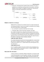
Page 14: ...ee system In this sys tem Relevant Command is returned to a common node or root so that a sub system is formed A part of OUTPut subsystem is listed below OUTPut SYNC OFF 0 ON 1 SYNC MODE NORMal CARRie...

Page 15: ...path is a null string for each subsequent command the head path is a string which is defined to form the current command until and including the head of the last co lon separator A message with two co...

Page 16: ...mmands in the same message Treat the common command as a message unit by separating it with a semicolon the message unit separator Common commands do not affect the header path you may insert them any...

Page 17: ...types of SCPI messages program and response Program message A program message consists of one or more properly formatted SCPI commands sent from the controller to the instrument The message which may...

Page 18: ...message units are combined into a compound message separate the units with a semicolon STATus OPERation QUEStionable Root specifier When it precedes the first header of a message unit the colon become...

Page 19: ...Response messages A response message is the message sent by the instrument to the computer in response to a query command Sending a response message After sending a query command the response message...

Page 20: ...URce 1 2 FREQuency CENTer frequency MINimum MAXimum DEFault Based on the command syntax most commands and certain Parameter are expressed in both upper and lower cases Upper case refers to abbreviatio...

Page 21: ...ion since the whole SOURce node is optional in the square bracket you can refer to the channel 1 by omitting the whole SOURce node It is be cause the channel 1 is the default channel for SOURce langua...

Page 22: ...follows RST CLS ESE 32 OPC Command terminator Command strings sent to the instrument must end with a Newline NL character IEEE 488 EOI End or Identify information can be used as NL character to repla...

Page 23: ...number in scientific notation such as 2 73E 2 Nrf The extensible form includes NR1 NR2 and NR3 Nrf The extensible decimal form includes Nrf MIN MAX and DEF MIN and MAX are the minimum and maximum fini...

Page 24: ...lowing commands display message of WAITING without quotation marks on the front panel of the instrument DISP TEXT WAITING Single quotation marks may also be used to display the same message DISP TEXT...

Page 25: ...us when the instrument is powered on is equivalent to executing the RST command For details see RST SAV0 The parameter setting or status when the instrument is powered on is equivalent to executing th...

Page 26: ...e instrument is powered on Group System Syntax SYSTem POSetup Arguments None Default Value None Returns CPD RST SAV0 Example SYST POS Also see None SYSTem VERSion The command returns a string in the f...

Page 27: ...e to read an error message from the error queue The front panel ERROR annunciator turns on when one or more errors are currently stored in the error queue Error retrieval is first in first out FIFO an...

Page 28: ...ueue SYSTem CLEar This command is used to clear the error queue Group System Syntax SYST CLE Arguments None Default Value None Returns None Example SYST CLE Also see None SYSTem REMote This command is...

Page 29: ...s None Example SYST REM Also see None SYSTem LOCal This command is used to set the instrument to local mode i e panel control mode All keys on the front panel will be available after executing this co...

Page 30: ...ple SYST LOC Also see None SYSTem RWLock This command is used to set the device to the remote state and lock the local keys Group System Syntax SYST RWL Arguments None Default Value None Returns None...

Page 31: ...set the buzzer to make a beep Group System Syntax SYST BEEP IMM Arguments None Default Value None Returns None Example SYST BEEP IMM Also see None SYSTem BEEPer STATe CPD This command is used to set...

Page 32: ...lue ON Returns None Example SYST BEEP OFF Also see SYSTem BEEPer STATe SYSTem BEEPer STATe This command is used to query the status of the buzzer enable or disable Group System Syntax SYSTem BEEPer ST...

Page 33: ...et the date of the system clock Specify the number of years 2000 to 2099 the number of months 1 to 12 and the number of days 1 to 31 Group System Syntax SYSTem DATE yyyy mm dd Arguments NR1 Default Va...

Page 34: ...None Returns SRD yyyy mm dd Example SYST DATE Also see None SYSTem TIME hh mm ss This command is used to set the time of the system clock Specify the number of hours 0 to 23 minutes 0 to 59 and secon...

Page 35: ...SPD Default Value 12 30 01 Returns None Example Set the clock to 8 30 PM SYST TIME 20 30 0 Also see SYSTem TIME SYSTem TIME This command is used to query the time of the system clock Group System Syn...

Page 36: ...faces USB LAN VCP and CAN and supports two optional communication interfaces GPIB RS 232 And the RS232 and GPIB options can be selected only after the communication board corresponding to RS232 and GP...

Page 37: ...cate SELect SYSTem COMMunicate SELect This command is used to query the currently selected communication interface Group System Syntax SYSTem COMMunicate SELect Arguments None Default Value None Retur...

Page 38: ...unicate GPIB ADDRess NR1 Arguments NR1 Setting range 1 to 30 Default Value 1 Returns None Example SYST COMM GPIB ADDR 2 Also see SYSTem COMMunicate GPIB ADDRess SYSTem COMMunicate GPIB ADDRess This co...

Page 39: ...Also see None SYSTem COMMunicate SERial BAUDrate CPD This command is used to set the baud rate of RS232 interface Group System Syntax SYSTem COMMunicate SERial BAUDrate CPD Arguments CPD 115200 57600...

Page 40: ...OMMunicate SERial BAUDrate This command is used to query the currently RS232 baud rate Group System Syntax SYSTem COMMunicate SERial BAUDrate Arguments None Default Value None Returns CRD 115200 57600...

Page 41: ...N IP CONFiguration SPD Arguments SPD Default Value 192 168 0 10 Returns None Example SYST COMM LAN IP 192 168 0 11 Also see SYSTem COMMunicate LAN IP CONFiguration SYSTem COMMunicate LAN IP CONFigurat...

Page 42: ...on MODE CPD This command is used to set the IP mode of the LAN port Manual The user manually sets the IP related parameters AUTO The system automatically configures IP related parameters Group System...

Page 43: ...uration MODE SYSTem COMMunicate LAN IP CONFiguration MODE This command is used to query the IP mode of the LAN port Group System Syntax SYSTem COMMunicate LAN IP CONFiguration MODE Arguments None Defa...

Page 44: ...yntax SYSTem COMMunicate LAN SMASk SPD Arguments SPD Default Value 255 255 255 0 Returns None Example SYST COMM LAN SMAS 255 255 255 1 Also see SYSTem COMMunicate LAN SMASk SYSTem COMMunicate LAN SMAS...

Page 45: ...rns SRD Example SYST COMM LAN SMAS Also see None SYSTem COMMunicate LAN DGATeway SPD This command is used to set the gateway address of the LAN communication Group System Syntax SYSTem COMMunicate LAN...

Page 46: ...N DGAT SYSTem COMMunicate LAN DGATeway This command is used to query the gateway address of the LAN communication Group System Syntax SYSTem COMMunicate LAN DGATeway Arguments None Default Value None...

Page 47: ...to the Idle state ABORt ACQuire Cancel any triggered measurement i e discard the present measurement Group ABORt Syntax ABORt ACQuire Arguments None Default Value None Returns None Example ABOR ACQ Al...

Page 48: ...ABORt Subsystem Group ABORt Syntax ABORt ARB Arguments None Default Value None Returns None Example ABOR ARB Also see None Copyright Itech Electronic Co Ltd 35...

Page 49: ...he instrument to be ready to receive a trigger signal after receiving the INITiate command If a trigger occurs before the trigger system is ready for it the trigger will be ignored Use ABORt commands...

Page 50: ...te ARB Arguments None Default Value None Returns None Example INIT ARB Also see None INITiate CONTinuous ARB Bool This command is used to enable or disable the ARB continuous trigger function Use occa...

Page 51: ...Value 0 OFF Returns None Example INIT CONT ARB 1 Also see INITiate CONTinuous ARB INITiate CONTinuous ACQuire Bool This command is used to enable or disable the Meter continuous trigger function Grou...

Page 52: ...INITiate Subsystem 0 OFF 1 ON Default Value 1 ON Returns None Example INIT CONT ACQ 0 Also see INITiate CONTinuous ACQuire Copyright Itech Electronic Co Ltd 39...

Page 53: ...used to set the pin number of the digital I O interface Pins 1 to 7 correspond to number 0 to 6 Group CONFigurable Syntax CONFigurable IO SELect NR1 Arguments NR1 The setting range is from 0 to 6 Defa...

Page 54: ...None Returns NR1 The range is from 0 to 6 Example IO SEL Also see None CONFigurable IO DIRection NRL Bool This command is used to set the direction of the digital signal of the specified pin NRL Used...

Page 55: ...Arguments NRL Bool 0 to 6 0 OUT 1 IN Default Value 0 0 OUT Returns None Example Set the pin 1 as the signal input IO DIR 0 1 Also see CONFigurable IO DIRection NRL CONFigurable IO DIRection NRL This c...

Page 56: ...command is used to control whether the digital signal of the specified pin is inverted NRL Used to specify the pin number Pins 1 to 7 correspond to number 0 to 6 Bool Used to control whether the digit...

Page 57: ...ignal of the pin 1 IO REV 0 1 Also see CONFigurable IO REVerse NRL CONFigurable IO REVerse NRL This command is used to query whether the digital signal of the specified pin is inverted Group CONFigura...

Page 58: ...on of the specified pin is turned on NRL Used to specify the pin number Pins 1 to 7 correspond to number 0 to 6 Bool Used to control whether the PWM function of the specified pin is turned on 0 OFF No...

Page 59: ...able IO PWM ENABle NRL CONFigurable IO PWM ENABle NRL This command is used to query the PWM function switch status of the specified pin Group CONFigurable Syntax CONFigurable IO PWM ENABle NRL Argumen...

Page 60: ...ified pin Group CONFigurable Syntax CONFigurable IO PWM FREQuency NRL NRf Arguments NRL NRf 0 to 6 MINimum MAXimum DEFault value Value range 2 to 21KHz Default Value 0 0 Returns None Example Set the P...

Page 61: ...n Group CONFigurable Syntax CONFigurable IO PWM FREQuency NRL MINimum MAXimum DEFault Arguments NRL MINimum MAXimum DEFault Default Value None Returns NRf Example IO PWM FREQ 1 Also see None CONFigura...

Page 62: ...None Example Set the PWM duty cycle of the pin 1 to 10 IO PWM DUTY 0 10 Also see CONFigurable IO PWM DUTY NRL CONFigurable IO PWM DUTY NRL This command is used to query the PWM duty cycle of the spec...

Page 63: ...L NRf This command is used to set the pulse width of the specified pin Group CONFigurable Syntax CONFigurable IO PULSe WIDTh NRL NRf Arguments NRL NRf 0 to 6 MINimum MAXimum DEFault value Default Valu...

Page 64: ...urable Syntax CONFigurable IO PULSe WIDTh NRL MINimum MAXimum DEFault Arguments NRL MINimum MAXimum DEFault Default Value None Returns NRf Example IO PULS WIDT 1 Also see None CONFigurable IO TYPE NRL...

Page 65: ...cify the pin number Pins 1 to 7 correspond to number 0 to 6 CPD Used to specify the pin function First function correspond to pin 1 to 7 PSCLear PSSTa OFFSta EXTTrig TOUT INHLiv INHLat SYON SYOFF Seco...

Page 66: ...Corresponds to the default function of pin 4 Indicates that when the instrument generates a trigger signal trigger Meter data logging or List function running a pulse signal will be output from pin 4...

Page 67: ...type of pin 4 TOUT When the instrument generates a trigger signal trigger Meter data logging or List function running a pulse signal will be output from pin 4 TIN Indicates that the instrument will t...

Page 68: ...ONFigurable IO TRIGger TYPE CONFigurable IO TRIGger TYPE This command is used to query the Ext Trig function type of pin 4 Group CONFigurable Syntax CONFigurable IO TRIGger TYPE Arguments None Default...

Page 69: ...tion DLOG Triggers the running of the data logging function LIST Triggers the running of the list function Group CONFigurable Syntax CONFigurable IO TRIGin SOURce CPD Arguments CPD METEr DLOG LIST Def...

Page 70: ...rable Syntax CONFigurable IO TRIGin SOURce Arguments None Default Value None Returns CRD METEr DLOG LIST Example IO TRIG SOUR Also see None CONFigurable IO OUTPut LEVel NRL CPD This command is used to...

Page 71: ...Returns None Example IO OUTP LEV 1 0 Also see CONFigurable IO OUTPut LEVel NRL CONFigurable IO OUTPut LEVel NRL This command is used to query the output of the specified pin is a high level or a low...

Page 72: ...see None CONFigurable IO INPut LEVel NRL This command is used to query the input of the specified pin is a high level or a low level Group CONFigurable Syntax CONFigurable IO INPut LEVel NRL Argument...

Page 73: ...CONFigurable Subsystem Example IO INP LEV 1 Also see None Copyright Itech Electronic Co Ltd 60...

Page 74: ...IMMediate This command is used to generate a trigger for the Meter function When the Meter function is triggered the instrument will display the voltage current meas urement in real time Group TRIGger...

Page 75: ...e when the instrument re ceives a trigger signal from the trigger source Group TRIGger Syntax TRIGger ACQuire MODE CPD Arguments CPD AUTO NORMal Default Value NORMal Example TRIGger ACQuire MODE AUTO...

Page 76: ...igure the relevant pa rameters of pin 4 For details please refer to the instruction of the CON Figurable subsystem BUS Command TRG triggering MANual Manual triggering that is the Meter function is tri...

Page 77: ...Gative Falling edge EITHer Both rising and falling edges Before executing this command you need to set the trigger source of the Meter function to voltage Group TRIGger Syntax TRIGger ACQuire VOLTage...

Page 78: ...e trigger threshold of the Meter Group TRIGger Syntax TRIGger ACQuire VOLTage LEVel NRf Arguments NRf MIN MAX DEF value Setting range MIN to MAX Default Value MIN Example TRIGger ACQuire VOLTage LEVel...

Page 79: ...sis HIGH NRf Arguments NRf MIN MAX DEF value Setting range MIN to MAX Default Value MIN Example TRIGger ACQuire VOLTage HYSTeresis HIGH 100 Query Syntax TRIGger ACQuire VOLTage HYSTeresis HIGH MIN MAX...

Page 80: ...uery Syntax TRIGger ACQuire VOLTage HYSTeresis LOW MIN MAX DEF Returns NRf MIN MAX DEF value TRIGger ACQuire CURRent SLOPe CPD This command is used to set the current trigger edge of the Meter POSitiv...

Page 81: ...itive Example TRIGger ACQuire CURRent SLOPe NEGative Query Syntax TRIGger ACQuire CURRent SLOPe Returns CRD POSitive NEGative EITHer TRIGger ACQuire CURRent LEVel NRf This command is used to set the c...

Page 82: ...ntax TRIGger ACQuire CURRent LEVel MIN MAX DEF Returns NRf MIN MAX DEF value TRIGger ACQuire CURRent HYSTeresis HIGH NRf This command is used to set the current trigger high threshold Group TRIGger Sy...

Page 83: ...rns NRf MIN MAX DEF value TRIGger ACQuire CURRent HYSTeresis LOW NRf This command is used to set the current trigger low threshold Group TRIGger Syntax TRIGger ACQuire CURRent HYSTeresis LOW NRf Argum...

Page 84: ...RIGger ARB IMMediate This command is used to generate a trigger for the ARB subsystem function For example trigger the output of LIST car waveform etc Group TRIGger Syntax TRIGger ARB IMMediate Argume...

Page 85: ...to configure the relevant pa rameters of pin 4 For details please refer to the instruction of the CON Figurable subsystem BUS Triggered by the command TRG MANual Manual triggering that is the ARB subs...

Page 86: ...passes to the event register When a PTR bit is set signals with positive edge transition pass to the event register When an NTR bit is set signals with a negative edge transition pass to the event reg...

Page 87: ...eads the MSS in bit position 6 of the response but does not clear any of the bits in the Status Byte register The RQS bit is a latched version of the MSS bit Whenever the instrument re quests service...

Page 88: ...048 Externally inhibited output PS 12 4096 Fault protection bit protect shutdown OSC 13 8192 Loop oscillation failure UNR 14 16384 Unknown internal fault of the instrument Operation Status Bit ACQ WTG...

Page 89: ...for the Questionable Status group This is a read only register which stores latches all events that are passed by the Operation NTR and or PTR filter Reading the Questionable Status Event register cl...

Page 90: ...questionable summary bit of the Status Byte register STATus PRESet clears all bits in the enable register CLS does not clear the enable register but does clear the event register Group STATus Syntax S...

Page 91: ...bit in the Questionable Condition register causes that bit in the Questionable Event register to be set STATus PRESet sets all bits in the PTR registers and clears all bits in the NTR registers Group...

Page 92: ...isters If the same bits in both NTR and PTR registers are set to 1 then any transi tion of that bit at the Questionable Condition register sets the corresponding bit in the Questionable Event register...

Page 93: ...ment Reading the Questionable Status Condition register does not clear it The value returned is the binary weighted sum of all enabled bits in the register For example with bit 2 value 4 and bit 4 val...

Page 94: ...passed by the Operation NTR and or PTR filter Reading the Operation Status Event register clears it The value returned is the binary weighted sum of all enabled bits in the register For example with...

Page 95: ...of the Status Byte register STATus PRESet clears all bits in the enable register CLS does not clear the enable register but does clear the event register Group STATus Syntax STATus OPERation ENABle NR...

Page 96: ...tion Condition register causes that bit in the Operation Event register to be set STATus PRESet sets all bits in the PTR registers and clears all bits in the NTR registers Group STATus Syntax STATus O...

Page 97: ...1 then any transi tion of that bit at the Operation Condition register sets the corresponding bit in the Operation Event register If the same bits in both NTR and PTR registers are set to 0 then no tr...

Page 98: ...weighted sum of all enabled bits in the register For example with bit 3 value 8 and bit 5 value 32 set and en abled the query returns 40 The condition register bits reflect the current condition If a...

Page 99: ...NAB STAT QUES ENAB All defined bits are disabled STAT OPER NTR STAT QUES NTR All defined bits are disabled STAT OPER PTR STAT QUES PTR All defined bits are disabled Group STATus Syntax STATus PRESet A...

Page 100: ...STATus Subsystem Also see None Copyright Itech Electronic Co Ltd 87...

Page 101: ...urement calculations from the same acquired data The data is valid until the next MEASure or INITiate command occurs FETCh SCALar CURRent DC This command is used to get the average value of the Meter...

Page 102: ...FETCh Syntax FETCh SCALar CURRent DC HIGH Arguments None Default Value None Returns NRf Example FETCh SCALar CURRent DC HIGH Also see None FETCh SCALar CURRent DC LOW Returns the Low level of a pulse...

Page 103: ...h SCALar CURRent DC LOW Also see None FETCh SCALar CURRent DC MAXimum Returns the maximum value of Meter current Values returned in amperes Group FETCh Syntax FETCh SCALar CURRent DC MAXimum Arguments...

Page 104: ...ue of Meter current Values returned in amperes Group FETCh Syntax FETCh SCALar CURRent DC MINimum Arguments None Default Value None Returns NRf Example FETCh SCALar CURRent DC MINimum Also see None FE...

Page 105: ...Default Value None Returns NRf Example FETCh SCALar VOLTage DC Also see None FETCh SCALar VOLTage DC HIGH Returns the High level of a pulse waveform Values returned in volts Group FETCh Syntax FETCh S...

Page 106: ...HIGH Also see None FETCh SCALar VOLTage DC LOW Returns the Low level of a pulse waveform Values returned in volts Group FETCh Syntax FETCh SCALar VOLTage DC LOW Arguments None Default Value None Retur...

Page 107: ...urned in volts Group FETCh Syntax FETCh SCALar VOLTage DC MAXimum Arguments None Default Value None Returns NRf Example FETCh SCALar VOLTage DC MAXimum Also see None FETCh SCALar VOLTage DC MINimum Re...

Page 108: ...Value None Returns NRf Example FETCh SCALar VOLTage DC MINimum Also see None FETCh SCALar POWer DC This command is used to get the average value of the Meter power Group FETCh Syntax FETCh SCALar POW...

Page 109: ...h SCALar POWer DC MAXimum Returns the maximum value of Meter power Values returned in watts Group FETCh Syntax FETCh SCALar POWer DC MAXimum Arguments None Default Value None Returns NRf Example FETCh...

Page 110: ...NRf Example FETCh SCALar POWer DC MINimum Also see None FETCh ARRay CURRent DC start_index points Returns the instantaneous measurement Values returned in amperes Optional parameters specify a subset...

Page 111: ...None FETCh ARRay VOLTage DC start_index points Returns the instantaneous measurement Values returned in volts Optional pa rameters specify a subset starting at startindex and of length points Data is...

Page 112: ...aneous measurement Values returned in watts Optional pa rameters specify a subset starting at startindex and of length points Data is returned as single precision floating point values in a finite len...

Page 113: ...FETCh ARRay POWer DC Also see None FETCh SCALar This command is used to obtain a variety of data voltage current power Group FETCh Syntax FETCh SCALar Arguments None Default Value None Returns NRf Ex...

Page 114: ...p FETCh Syntax FETCh ACMeter EACStage Arguments None Default Value None Returns NRf Example FETCh ACMeter EACStage Also see None FETCh ACMeter EACTotal This command is used to read the total historica...

Page 115: ...FETCh Subsystem Arguments None Default Value None Returns NRf Example FETCh ACMeter EACTotal Also see None Copyright Itech Electronic Co Ltd 102...

Page 116: ...e or current for a specified measurement time storing the results in a buffer and calculating the value for the specified measurement type MEASure SCALar CURRent DC Initiates triggers and returns the...

Page 117: ...in amperes Group MEASure Syntax MEASure SCALar CURRent HIGH Arguments None Default Value None Returns NRf Example MEASure SCALar CURRent HIGH Also see None MEASure SCALar CURRent LOW Initiates trigge...

Page 118: ...ple MEASure SCALar CURRent LOW Also see None MEASure SCALar CURRent MAXimum Initiates triggers and returns the maximum values of a current measurement Values returned in amperes Group MEASure Syntax M...

Page 119: ...ent MINimum Initiates triggers and returns the minimum values of a current measurement Values returned in amperes Group MEASure Syntax MEASure SCALar CURRent MINimum Arguments None Default Value None...

Page 120: ...d in volts Group MEASure Syntax MEASure SCALar VOLTage DC Arguments None Default Value None Returns NRf Example MEASure SCALar VOLTage DC Also see None MEASure SCALar VOLTage HIGH Initiates triggers a...

Page 121: ...s NRf Example MEASure SCALar VOLTage HIGH Also see None MEASure SCALar VOLTage LOW Initiates triggers and returns the Low level of a pulse waveform Values re turned in volts Group MEASure Syntax MEASu...

Page 122: ...ge MAXimum Initiates triggers and returns the maximum values of a voltage measurement Values returned in volts Group MEASure Syntax MEASure SCALar VOLTage MAXimum Arguments None Default Value None Ret...

Page 123: ...eturned in volts Group MEASure Syntax MEASure SCALar VOLTage MINimum Arguments None Default Value None Returns NRf Example MEASure SCALar VOLTage MINimum Also see None MEASure SCALar POWer DC Initiate...

Page 124: ...Example MEASure SCALar POWer DC Also see None MEASure SCALar POWer MAXimum Initiates triggers and returns the maximum values of a power measurement Values returned in watts Group MEASure Syntax MEASur...

Page 125: ...POWer MINimum Initiates triggers and returns the minimum values of a power measurement Values returned in watts Group MEASure Syntax MEASure SCALar POWer MINimum Arguments None Default Value None Retu...

Page 126: ...p MEASure Syntax MEASure ARRay CURRent DC Arguments None Default Value None Returns Block Example Returns the measured current array MEASure ARRay CURRent DC Also see None MEASure ARRay VOLTage DC Ini...

Page 127: ...e MEASure ARRay POWer DC Initiates and triggers a power measurement returns a list of the digitized power measurement samples Values returned in watts Data is returned as single pre cision floating po...

Page 128: ...ure ARRay POWer DC Also see None MEASure SCALar This command is used to measure a variety of data voltage current power Group MEASure Syntax MEASure SCALar Arguments None Default Value None Returns NR...

Page 129: ...CPD This command is used to select the instrument role in the case of parallel SINGle Single mode SLAVe Slave mode MASTer Master mode Group PARallel Syntax PARallel ROLE CPD Arguments CPD SINGle SLAVe...

Page 130: ...total number of instruments in the case of par allel i e the sum of the masters and slaves Group PARallel Syntax PARallel NUMBer NR1 Arguments NR1 Setting range 1 to 8 Default Value 1 Example PARalle...

Page 131: ...ce REMote SENSe STATe Bool This command is used to set the on off state of the Sense function 0 OFF Turn off 1 ON Turn on Group SENSe Syntax SOURce REMote SENSe STATe Bool Arguments Bool 0 OFF 1 ON De...

Page 132: ...e Syntax SENSe ACQuire POINts NRf Arguments NRf MIN MAX DEF value Setting range MIN to MAX Default Value MIN Example SENSe ACQuire POINts 50 Query Syntax SENSe ACQuire POINts MIN MAX DEF Returns NRf S...

Page 133: ...ENSe ACQuire OFFSet POINt 10 Query Syntax SENSe ACQuire OFFSet POINt MIN MAX DEF Returns NRf SENSe ACQuire TINTerval NRf This command is used to set the sampling time interval of the Meter module Grou...

Page 134: ...SENSe Subsystem Default Value MIN Example SENSe ACQuire TINTerval 0 1 Query Syntax SENSe ACQuire TINTerval MIN MAX DEF Returns NRf Copyright Itech Electronic Co Ltd 121...

Page 135: ...Rce VOLTage UNDer PROTection STATe Bool SOURce VOLTage UNDer PROTection LEVel NRf SOURce VOLTage UNDer PROTection DELay NRf SOURce VOLTage UNDer PROTection WARM NRf SOURce RESistance LEVel IMMediate A...

Page 136: ...le SOUR FUNC VOLT Query Syntax SOURce FUNCtion Returns VOLTage CURRent POWer RESistance CVCC CRCC CVCR AUTO 12 2 SOURce LOOP SPEed CPD This command is used to set the loop speed of the load Group SOUR...

Page 137: ...value indicates that the instrument is operating in fixed mode Keeps the input current at its immediate value ARB Indicates that the instrument is operating in ARB mode When a trigger occurs ARB will...

Page 138: ...This command is used to set the input current value in CC operation mode Group SOURce Syntax SOURce CURRent LEVel IMMediate AMPLitude NRf Arguments NRf MINimum MAXimum DEFault value Setting range MIN...

Page 139: ...and take effect at the same time Group SOURce Syntax SOURce CURRent SLEW BOTH NRf Arguments NRf MINimum MAXimum DEFault value Setting range MIN MAX Default Value None Example CURR SLEW BOTH 1 Query S...

Page 140: ...value Setting range MIN to MAX Default Value None Example CURR SLEW POS 1 Query Syntax SOURce CURRent SLEW POSitive Returns NRf 12 7 SOURce CURRent SLEW NEGative NRf This command is used to set the c...

Page 141: ...nt SLEW NEGative Returns NRf 12 8 SOURce CURRent OVER PROTection STATe Bool Enable or disable overcurrent protection If the overcurrent protection function is enabled and the input enters a current li...

Page 142: ...12 9 SOURce CURRent OVER PROTection LEVel NRf This command is used to set the limit value of overcurrent protection Group SOURce Syntax SOURce CURRent OVER PROTection LEVel NRf Arguments NRf MINimum...

Page 143: ...mand is used to set the delay time of overcurrent protection Group SOURce Syntax SOURce CURRent OVER PROTection DELay NRf Arguments NRf MINimum MAXimum DEFault value Setting range MIN to MAX Default V...

Page 144: ...e NRf Arguments NRf MINimum MAXimum DEFault value Setting range MIN to MAX Default Value None Example VOLT 5 Query Syntax SOURce VOLTage LEVel IMMediate AMPLitude Returns NRf 12 12 SOURce VOLTage SLEW...

Page 145: ...Default Value None Example VOLT SLEW BOTH 1 Query Syntax SOURce VOLTage SLEW BOTH Returns NRf 12 13 SOURce VOLTage SLEW POSitive NRf This command is used to set the voltage rise time Group SOURce Syn...

Page 146: ...ce VOLTage SLEW POSitive Returns NRf 12 14 SOURce VOLTage SLEW NEGative NRf This command is used to set the voltage fall time Group SOURce Syntax SOURce VOLTage SLEW NEGative NRf Arguments NRf MINimum...

Page 147: ...age ON LEVel NRf This command is used to set the start load voltage of the load Group SOURce Syntax SOURce VOLTage ON LEVel NRf Arguments NRf MINimum MAXimum DEFault value Setting range MIN to MAX Def...

Page 148: ...oltage protection is enabled and the input reaches the voltage limit the input is disabled Group SOURce Syntax SOURce VOLTage UNDer PROTection STATe Bool Arguments Bool 0 OFF 1 ON Default Value 0 OFF...

Page 149: ...OLTage UNDer PROTection LEVel NRf Arguments NRf MINimum MAXimum DEFault value Setting range MIN to MAX Default Value None Example VOLT UND PROT 5 Query Syntax SOURce VOLTage UNDer PROTection LEVel Ret...

Page 150: ...MIN to MAX Default Value None Example VOLT UND PROT DEL 10 Query Syntax SOURce VOLTage UNDer PROTection DELay Returns NRf 12 19 SOURce VOLTage UNDer PROTection WARM NRf This command is used to set the...

Page 151: ...e VOLTage UNDer PROTection WARM Returns NRf 12 20 SOURce RESistance LEVel IMMediate AMPLitude NRf This command is used to set the input resistance value in CR operation mode Group SOURce Syntax SOURce...

Page 152: ...12 21 SOURce POWer LEVel IMMediate AMPLitude NRf This command is used to set the power value in CW operation mode Group SOURce Syntax SOURce POWer LEVel IMMediate AMPLitude NRf Arguments NRf MINimum...

Page 153: ...able over power protection If power protection is enabled and the input reaches the power limit the input is disabled Group SOURce Syntax SOURce POWer PROTection STATe bool Arguments Bool 0 OFF 1 ON D...

Page 154: ...x SOURce POWer PROTection LEVel NRf Arguments NRf MINimum MAXimum DEFault value Setting range MIN to MAX Default Value None Example POW PROT 10 Query Syntax SOURce POWer PROTection LEVel Returns NRf 1...

Page 155: ...t Value None Example POW PROT DEL 5 Query Syntax SOURce POWer PROTection DELay Returns NRf 12 25 SOURce POWer SLEW BOTH NRf This command is used to set the power rise and fall time that is the two tim...

Page 156: ...BOTH 1 Query Syntax SOURce POWer SLEW BOTH Returns NRf 12 26 SOURce POWer SLEW POSitive NRf This command is used to set the power rise time Group SOURce Syntax SOURce POWer SLEW POSitive NRf Argument...

Page 157: ...Wer SLEW NEGative NRf This command is used to set the power fall time Group SOURce Syntax SOURce POWer SLEW NEGative NRf Arguments NRf MINimum MAXimum DEFault value Setting range MIN MAX Default Value...

Page 158: ...Group SOURce Syntax SOURce VOLTage ON LATCh STATe Bool Arguments Bool 0 OFF 1 ON Default Value None Example VOLT LATCh 1 Query Syntax SOURce VOLTage ON LATCh STATe Returns 0 1 12 29 SOURce VOLTage ON...

Page 159: ...Fault value Setting range MIN to MAX Default Value None Example VOLT ON HYST 5 Query Syntax SOURce VOLTage ON HYSTeresis LEVel Returns NRf 12 30 SOURce EXTern STATe Bool This command is used to set th...

Page 160: ...ntax SOURce EXTern STATe Returns 0 1 12 31 SOURce ACMeter EACStage CLEar Resets the total regenerative power to zero Group SOURce Syntax SOURce ACMeter EACStage CLEar Arguments None Default Value None...

Page 161: ...SOURce Subsystem Query Syntax None Returns None Copyright Itech Electronic Co Ltd 148...

Page 162: ...e INPut DELay RISE NRf SOURce INPut SHORt STATe CPD 13 1 SOURce INPut STATe CPD Enable or disable the input Group INPut Syntax SOURce INPut STATe CPD Arguments CPD 0 OFF 1 ON Default Value 0 OFF Examp...

Page 163: ...Rce INPut DELay FALL NRf Arguments NRf MINimum MAXimum DEFault value Setting range MIN to MAX Default Value DEFault 0 Example INP DEL FALL 6 Query Syntax SOURce INPut DELay FALL Returns NRf 13 3 SOURc...

Page 164: ...Setting range MIN to MAX Default Value DEFault 0 Example INP DEL RISE 5 Query Syntax SOURce INPut DELay RISE Returns NRf 13 4 SOURce INPut SHORt STATe CPD Enable or disable the short mode Group INPut...

Page 165: ...INPut Subsystem Default Value 0 OFF Example INP SHOR 1 Query Syntax SOURce INPut SHORt STATe Returns 0 1 Copyright Itech Electronic Co Ltd 152...

Page 166: ...mand is used to set the capacitance value of the battery test cutoff Group BATTery Syntax BATTery SHUT CAPacity NRf Arguments NRf MINimum MAXimum DEFault value Setting range MIN to MAX Default Value D...

Page 167: ...ments NRf MINimum MAXimum DEFault value Setting range MIN to MAX Default Value DEFault 20 s Example BATTery SHUT TIME 3 Query Syntax BATTery SHUT TIME Returns NRf MINimum MAXimum DEFault value 14 3 BA...

Page 168: ...age NRf Arguments NRf MINimum MAXimum DEFault value Setting range MIN to MAX Default Value DEFault 0 Example BATT SHUT VOLT 200 Query Syntax BATTery SHUT VOLTage Returns NRf MINimum MAXimum DEFault va...

Page 169: ...COUNt NR1 This command is used to set the total number of steps in the LIST Before set ting the amplitude time width and slope you must execute this command firstly to set the total number of steps in...

Page 170: ...ments CPD VOLTage CURRent POWer RESistance Default Value VOLTage Example ARB FUNCtion CURRent Query Syntax ARB FUNCtion Returns CRD VOLTage CURRent POWer RESistance 15 3 ARB UDEFined LEVel NR1 NRf Thi...

Page 171: ...ting range MIN to MAX Example ARB UDEFined LEVel 2 10 Query Syntax ARB UDEFined LEVel NR1 Query by specifying a step number to return the amplitude corresponding to the step in the LIST waveform Retur...

Page 172: ...umber to return the time width corresponding to the step in the LIST waveform Returns NRf 15 5 ARB UDEFined SLEW NR1 NRf This command is used to set the slope corresponding to the X step of the user d...

Page 173: ...corresponding to the step in the LIST waveform Returns NRf 15 6 ARB COUNt NRf Specifies the number of times the Arb repeats Use the INFinity parameter or set as 0 to repeat the Arb continuously Group...

Page 174: ...e ARB waveform file Group ARB Syntax ARB SAVE NR1 Arguments NR1 The setting range is from 1 to 10 Example ARB SAVE 2 Query Syntax None Returns None 15 8 ARB RECall NR1 This command is used to recall t...

Page 175: ...ARB Subsystem Group ARB Syntax ARB RECall NR1 Arguments NR1 The setting range is from 1 to 10 Example ARB RECall 2 Query Syntax None Returns None Copyright Itech Electronic Co Ltd 162...

Page 176: ...mnemonic preceded by an asterisk RST IDN SRE 8 CLS Clear Status Command Clears the event registers in all register groups Also clears the status byte and error queue If CLS immediately follows a progr...

Page 177: ...reported to the ESB bit through the enable register To set the enable register mask write a decimal value to the register using ESE CLS does not clear the enable register but does clear the event regi...

Page 178: ...ESE Arguments None Default Value None Returns NR1 A decimal value corresponding to the binary weighted sum of the register s bits The range is from 0 to 255 Example ESE Also see None ESR Event status...

Page 179: ...query or CLS Group None Syntax ESR Arguments None Default Value None Returns NR1 Example ESR Also see None IDN Identification Query Returns instrument s identification string which contains four comm...

Page 180: ...ng operation The purpose of this command is to synchronize your application with the instrument Used in conjunction with initiated acquisitions transients output state changes and output settling time...

Page 181: ...n all pending operations complete The re sponse is delayed until all pending operations complete The purpose of this command is to synchronize your application with the instrument Other commands canno...

Page 182: ...t power on or after RST SCPI Commands RST Initial Settings ARB COUNt 1 ARB CURRent CDWell DWELl 0 001 ARB FUNCtion SHAPe CDW ARB FUNCtion TYPE VOLTage ARB TERMinate LAST OFF ARB VOLTage CDWell DWELl 0...

Page 183: ...ATe 0 TRIGger ACQuire CURRent 0 TRIGger ACQuire CURRent SLOPe POSitive TRIGger ACQuire SOURce BUS TRIGger ACQuire TOUTput OFF TRIGger ACQuire VOLTage 0 TRIGger ACQuire VOLTage SLOPe POSitive TRIGger A...

Page 184: ...etermines which bits from the Status Byte Register are summed to set the Master Status Summary MSS bit and the Request for Serv ice RQS summary bit A 1 in any Service Request Enable register bit posit...

Page 185: ...s bits The setting range is from 0 to 255 Default Value 0 Returns None Example Enable bit 3 and bit 4 in the enable register SRE 24 Also see SRE SRE Query the value of the service request enable regi...

Page 186: ...see None STB Status byte query Reads the Status Byte Register which contains the status summary bits and the Output Queue MAV bit The Status Byte is a read only register and the bits are not cleared...

Page 187: ...AV NR1 Save the instrument On Off status or several parameter settings to 10 non volatile memories and the position can be set from 0 to 9 When shipped loca tions 0 through 9 are empty If the PowerOn...

Page 188: ...ents NR1 The setting range is from 0 to 9 Default Value None Returns None Example SAV 2 Also see RCL NR1 RCL NR1 Recalls a saved instrument state This restores the instrument to a state that was previ...

Page 189: ...Also see SAV NR1 TST Self test query Performs a instrument self test If self test fails one or more er ror messages will provide additional information Use SYSTem ERRor to read error queue For detail...

Page 190: ...failed Example TST Also see None WAI Pauses additional command processing until all pending operations are complete Group None Syntax WAI Arguments None Default Value None Returns None Example WAI Als...

Page 191: ...instruction affects the value of the status register at the next powered on Group None Syntax PSC Bool Arguments Bool 0 OFF 1 ON Default Value 0 OFF Returns None Example PSC 1 Also see PSC PSC This in...

Page 192: ...IEEE 488 Common Commands Syntax PSC Arguments None Default Value None Returns Bool 0 OFF 1 ON Example PSC Also see None Copyright Itech Electronic Co Ltd 179...

Page 193: ...ROR Too many numeric suffices in Command Spec The number of numeric param eters of the command exceeds the limit 110 No Input Command to parse No command input for exam ple the error code is reported...

Page 194: ...gram only proc esses two 190 Too many dimensions in entry to be returned in parameters There are too many values re turned in the argument 191 Too many char The number of characters ex ceeds the limit...

Page 195: ...t device state A data element could not be executed because of the present instrument state 222 Data out of range e g too large for this device A data element could not be executed because the value w...

Page 196: ...DAB or GET before response complete A condition causing an inter rupted query error occurred 430 Query DEADLOCKED too many queries in command string A condition causing a dead locked query error occur...

Page 197: ...rror Digital I O self test error Device related errors 213 RS232 buffer overrun error RS232 buffer overflow 216 RS232 receiver framing error RS232 receiver frame error 217 RS232 receiver parity error...

Page 198: ...rrect An error occurred in reading the calibration data 405 Computed programming cal constants are incorrect An error occurred in calculating the calibration data 406 Incorrect sequence of calibra tio...

Page 199: ...nge Out of measurement range 605 Command not allowed while list initiated It is forbidden to execute this command while the List is initiated 610 Corrupt update data The system update data is corrupt...

Page 200: ...tact Us Thanks for purchasing ITECH products In case of any doubts please con tact us as follows 1 Visit ITECH website www itechate com 2 Select the most convenient contact method for further informat...

Reviews: