background image

A   D I V I S I O N   O F   T R I M B L E

1

875-0072-02 Rev B

Mercury

®

 xPRESS Platform Guide 

SDK Version 1.7.1

Summary of Contents for Mercury xPRESS

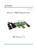
Page 1: ...A DIVISION OF TRIMBLE 1 875 0072 02 Rev B Mercury xPRESS Platform Guide SDK Version 1 7 1...

Page 2: ...d must also reproduce the markings Any person other than the U S Government who has been provided access to such data must promptly notify ThingMagic ThingMagic Mercury Reads Any Tag and the ThingMagi...

Page 3: ...ersion 1 5 1 875 0072 02 Rev A Sept 2014 Added SAM BA Appendix and changes introduced with revision 1 7 1 of the SDK plus hardware and software instructions for new WiFi POE and GPS modules 875 0072 0...

Page 4: ...A DIVISION OF TRIMBLE 4...

Page 5: ...s 15 Common Installation Best Practices 16 Quick Start Guide 17 xPRESS Platform Contents 18 Hardware 18 Software 19 Documentation 20 Hardware Setup 21 Using the Sample Application 25 RFID Sensor Appli...

Page 6: ...eatures Implemented 48 Initialization Process 50 Connection Status 52 Power Management 52 Console Command Control 53 Configuration Settings 54 Mapping of RN 171 Config Parameters to xPRESS Names 55 Kn...

Page 7: ...stalling JTAG ICE and J LINK GDB Server 91 Obtaining a JTAG ICE 91 JTAG Hardware Installation 92 Linux JLINK Software Installation JLinkGDBServer 92 Windows JLINK Software Installation JLinkGDBServer...

Page 8: ...ion 123 Li ion Battery 124 Comm Bus POE Power 124 Known HW Limitations 125 Known Issues 125 Software Reference Guide 127 SW Block diagram 127 Toolchain 128 Toolchain Downloads 128 Toolchain Build Inst...

Page 9: ...installing and operating the optional modules including Bluetooth WiFi Power Over Ethernet POE and GPS Installing Developer Tools on Windows OS This chapter provides detailed instructions for install...

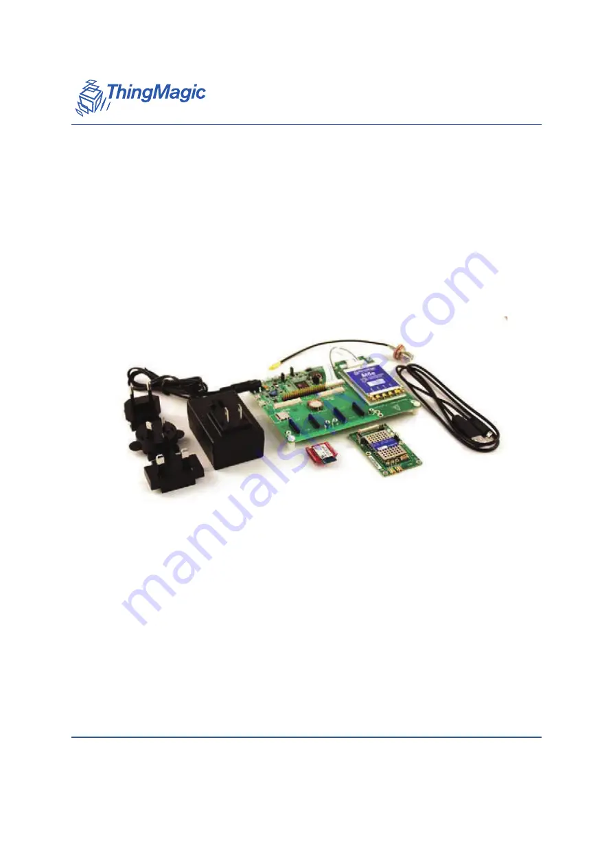
Page 10: ...le ThingMagic also offers RFID antennas and tags that are compatible with this platform See www thingmagic com for additional information Product Description Part Number xPRESS Development Platform wi...

Page 11: ...l categories of certification 1 Certification as an intentional radiator This category includes the following sub categories of requirements Correct in band characteristics to make it compatible with...

Page 12: ...of compliance that refers to these ID numbers if you are using our modular certification Included in the filing to the FCC is a calculation that shows the distance from the antenna that should be mai...

Page 13: ...to older requirements for a period of time The standard that covers UHF RFID is document number EN 302 208 and the current version is 1 4 1 The optional modules are certified to the following ETSI st...

Page 14: ...pproval when modular certification was obtained Micro and Micro LTE For circularly polarized antennas the maximum linear gain is the maximum gain as measured with a calibrated linear dipole antenna fa...

Page 15: ...ard ESD precautions should be taken during installation to avoid static discharge when handling or making connections to the reader antenna or communication ports Environmental analysis should also be...

Page 16: ...ostensibly on the outer surface of a single shield coaxial cable have been seen to couple to the inside of coaxial cables causing ESD failure Avoid RG 58 Prefer RG 223 Minimize ground loops in coaxia...

Page 17: ...SION OF TRIMBLE Quick Start Guide 17 Quick Start Guide This chapter provides a brief introduction to xPRESS with instructions to install setup and test the basic default functionality of the xPRESS Pl...

Page 18: ...ne of the optional module interfaces and add GPS location sensing If so consult the Using the Optional Modules section Use caution when configuring the hardware Note Always turn off the power and unpl...

Page 19: ...agic com manuals firmware The xPRESS platform is shipped with a demonstration application pre installed This application allows you to read RFID tags optionally add GPS information to the data receive...

Page 20: ...he ThingMagic support site using this URL http www thingmagic com manuals firmware This site also offers hardware design documentation that will allow you to develop your own processor board based on...

Page 21: ...e a different RFID module than the M6e shown here The following steps will take you through the hardware set up power up and connecting the xPRESS platform using its pre installed application which wi...

Page 22: ...e Connect your antenna to the other end of the cable though an R TNC to R TNC cable if necessary Make sure all the antenna cable connections are tight 3 Make sure the Flash Erase jumper is in the NORM...

Page 23: ...e is present Otherwise leave it in the position closest to the board edge and use the on off switch to control power to the system 7 Plug the AC adapter into the motherboard and connect it to an AC po...

Page 24: ...is actively reading The yellow LED will flash and the buzzer will chirp whenever a tag is read 11 If you wish to see status messages while the xPRESS platform is operating connect the second USB cabl...

Page 25: ...al application that we called the Keyboard Wedge The xPRESS platform will ship with this application pre installed and the source code for it will be included in the SDK Basic instructions for operati...

Page 26: ...with a minimum of effort The demonstration application simultaneously controls the RFID module maintains the active data interface and formats the data that is sent out that interface We call this a...

Page 27: ...onfigure_buttons which was called in task_wedge s initialization pin_edge_handler reads the current state of the read trigger button and sets the global activateTagReads accordingly task_rfid monitors...

Page 28: ...E_GPI_READ_WHILE_PRESSED Keep reading as long as trigger is held down ENABLE_GPI_READ_ON_OFF Toggle reading each time trigger is pulled ENABLE_GPI_READ_ONCE Read once for each trigger pull To change t...

Page 29: ...le using CLI command otherwise timestamp will start from default RTC value ie 2007 01 01 in Sensor output tag data format tag epc 0xdeadbeafdeadbeafdeadbeaf protocol GEN2 ant 1 readcount 5 rssi 79 fre...

Page 30: ...tem and maintenance utilities for the optional modules are supported as well Follow these steps to view the Console 1 Install the FTDI Virtual Com Port drivers for your OS http www ftdichip com Driver...

Page 31: ...FF 1 DEBUG loglevel value Expects one parameter 0 8 0 OFF 1 EMERG 2 ALERT 3 CRIT 4 ERR 5 WARNING 6 NOTICE 7 INFO 8 DEBUG peek address Expects one parameter poke address 32 bit data Expects two paramet...

Page 32: ...efault 0 0x80 Note I2C protocol analyzers see 0x78 0x7B as unknown 10 bit addresses since they start with the 10 bit address preamble 11110 twi read chipaddr addr len Read TWI I2C EEPROM twi write chi...

Page 33: ...ndicate action must be taken immediately loglevel 3 LOG_CRIT messages that indicate critical conditions loglevel 4 LOG_ERR messages that indicate error conditions loglevel 5 LOG_WARNING messages that...

Page 34: ...xPRESS Console A DIVISION OF TRIMBLE 34 Using the Sample Application Enter key and start again The backspace key does not erase previously typed characters...

Page 35: ...optional modules for the xPRESS platform There is also a common section on GPI management interaction among the modules Where necessary separate instructions are provided for setting up the xPRESS mod...

Page 36: ...can be ordered from ThingMagic as part number XP BT The full data sheet may be obtained here http ww1 microchip com downloads en DeviceDoc RN41XV RN42XV ds v1 0r pdf Hardware Installation 1 Disconnec...

Page 37: ...is blinking rapidly the module is in command mode Try rebooting the xPRESS motherboard to reset the Bluetooth module Linux Bluetooth Keyboard Setup For Linux Such as Ubuntu 10 04LTS 1 Plug in your Blu...

Page 38: ...ooth Module A DIVISION OF TRIMBLE 38 Using the Optional Modules 5 Click once to open a Bluetooth Devices window 6 Click Search When the Bluetooth device window appears right click on the Bluetooth add...

Page 39: ...Bluetooth Module A DIVISION OF TRIMBLE Using the Optional Modules 39 7 Select Pair If the pairing activity bar does not stop on its own just keep going...

Page 40: ...e colored bar graph appears you re ready You should also see a solid light on the Bluetooth module instead of blinking 10 Whenever the connection is broken the Bluetooth module will automatically atte...

Page 41: ...me will probably be RNBT nnnn where nnnn is the last 4 digits of the module s Bluetooth MAC address 5 Right click the device and select Properties Wait for the list of Bluetooth services to appear Che...

Page 42: ...screen Click BLUETOOTH 3 Pair with the Bluetooth module Click SEARCH FOR DEVICES Under AVAILABLE DEVICES at the bottom look for a device with the name RNBT nnnn where nnnn is the last 4 digits of the...

Page 43: ...ctions 1 Make sure there is no USB cable connected to the USBOTG interface It is OK if a cable is connected to the DEBUG Console interface After pairing the xPRESS platform will identify itself as a k...

Page 44: ...u change the demonstration application s initialization process for the Bluetooth module in order to put it in a different mode of operation RN 42 Initialization To reset the RN 42 Bluetooth module in...

Page 45: ...further RN 42 Connection Status The RN 42 sets Pin GPIO2 high when it is connected to another Bluetooth device This is important because it means you should not try to send commands to its UART If co...

Page 46: ...To enable the WiFi output interface the user may need to modify conf_xpress_reader h to disable other modules which are using the same XBee slot The required modifications in conf_xpress_reader h are...

Page 47: ...ED displays on the module indicate the following states for the module Green LED D1 is on when there is a connection to an access point Yellow LED D2 flashes whenever the xPRESS platform communicates...

Page 48: ...TCP client In this mode xPress behaves as both TCP server and TCP client To change the mode access point information Server IP details etc it is necessary to modify the configuration settings in the...

Page 49: ...emeral ports http en wikipedia org wiki Well known_ports Dynamic 2C_private_or_e phemeral_ports WIFLY_SUBNET_MASK 255 255 255 0 Required if WIFLY_DHCP_OFF WIFLY_GATEWAY_ADDRESS 192 168 0 1 Required if...

Page 50: ...WIFLY_TCP_SERVER_CLIENT WIFLY_HTTP_CLIENT WIFLY_DNS_NAME www posttestserver com HTTP web server name WIFLY_HTTP_SERVER_DIR xpr Directory name in HTTP web server Tags will be available in this directo...

Page 51: ...a Lost AP state and de authenticates It also sets the RSSI threshold level e WIFLY_setupTCPperformance sets the flush timer and flush size These are used for optimizing the TCP performance where flus...

Page 52: ...WIFLY_MonitorWiflyStatus which will be called by the task task_Wedge Note GPIO5 is not used as this pin is NC on xPRESS Reader Power Management RN 171 has the power features shown below Signal Name D...

Page 53: ...ion is re established Console Command Control The Console commands are configured in conf_xpress_reader h confINCLUDE_CLI_CMD_WIFLY_GET_NET_INFO This is used to activate Console commands to get networ...

Page 54: ...the RN 171 The CLI commands syntax wifly firmware update filename filename type is mif or img Configuration Settings To use RN 171 with xPRESS Reader enable configuration for output mechanism in conf_...

Page 55: ...orts Dynamic 2C_private_or_ephemeral_ports Mapping of RN 171 Config Parameters to xPRESS Names If you use the documentation for the RN 171 module to determine what configuration settings are supported...

Page 56: ...e value WIFLY_REMOTE_HOST_PORT_NUMBER set ip flags mask WIFLY_IP_FLAGS_MASK COMM UART COMM and UART Parameters set comm idle value WIFLY_TCP_IDLE_TIMER set comm size value WIFLY_FLUSH_SIZE set comm ti...

Page 57: ..._NUMBER set wlan auth value WIFLY_WLAN_AUTH Joining Networks set wlan join value Automated set as 1 Try to associate with the access point that matches the stored SSID pass key and channel If the chan...

Page 58: ...ote value WIFLY_REMOTE_HOST_PORT_NUMBER HTML HTML Client Web Server Modes set opt format flag WIFLY_HTTP_FORMAT_VALUE HTML Connect to a Web Server Automatically set sys autoconn value WIFLY_TCP_AUTO_C...

Page 59: ...ule wakeup from its sleep is not as per configuration setting WIFLY_TCP_WAKE_TIMER WiFly module goes to sleep mode depending on values defined for WIFLY_TCP_IDLE_TIMER and WIFLY_TCP_SLEEP_TIMER but th...

Page 60: ...ces to the xPRESS motherboard via SPI via the WIZnet provided open source reference drivers Installation Install the Ethernet module into slot 1 the right hand slot as you look at the board edge Note...

Page 61: ...MBLE Using the Optional Modules 61 PoE PoE NetInfo MAC 20 31 32 50 39 30 SIP 10 8 80 81 GAR 10 8 80 1 SUB 255 255 255 0 DNS 10 8 82 2 SPORT 49152 DHCP ON LEASE 691200 Sec In this example the IP addres...

Page 62: ...away from the edge of the board Note When power is supplied by the Ethernet port both the AC input and Li Ion battery are disconnected from the xPRESS power bus They are both still connected to each o...

Page 63: ...ace configured as HTTP client Note For HTTP client mode there is no need to use this combination with TCP as you must for the WiFi module If this mode is changed you will likely need to reconfigure th...

Page 64: ...n wikipedia org wiki Well known_ports Dynamic 2C_private_or_ephemeral_ports POE_REMOTE_HOST_HTTP_SERVER_DIR Applicable only for HTTP client mode Define the directory name which will be created in the...

Page 65: ...ow control is managed by wiznet library functions ex send and sendto If the socket is busy sending previous data POE_SendTagData handles re sending the data again Connection Status Monitors the connec...

Page 66: ...e qualified the LinkSprite GPS Bee module http store linksprite com gps bee sold by ThingMagic as part number XP GPS and one by Seeed Studio http www seeedstudio com depot GPS Bee kit with Mini Embedd...

Page 67: ...be included such as lat 42 286064 lon 71 071184 Note Once the GPS module has been enabled the GPS location or N A is always included in the tag string GPS Metadata The prefix and suffix for the GPS me...

Page 68: ...t format as below tag epc 0xdeadbeafdeadbeafdeadbeaf protocol GEN2 ant 1 readcount 5 rssi 79 frequency 926750 timestamp 2014 07 21T10 03 07 587 phase 2 gpio 1111 lat 17 260672 lon 78 236042 When the G...

Page 69: ...blinks its GPIO5 at different rates depending on its internal state This rate measurement could be useful in other places too so we don t limit its association to the Bluetooth driver Consumers of th...

Page 70: ...rPin uint32_t gpio_idx Used to unregister the GPI line that is being monitored bool GPIMGR_getValue uint32_t gpio_idx Used to get the GPI line current state uint32_t GPIMGR_getTogglePeriodMs uint32_t...

Page 71: ...in detail in the sections that follow Installing GNU Tools for ARM Embedded Processors 1 Download GNU Tools for ARM Embedded Processors Either the ZIP or EXE version can be used the EXE version is co...

Page 72: ...stall Java The Eclipse IDE which will be installed in the next step as Eclipse is a Java program You need to install a Java runtime before you can run it Version 1 7 or above is required Eclipse will...

Page 73: ...tall the 32 bit version if the browser you are using supports 32 bits Follow the on line instructions to manually install the version you need Download and install the latest Java Runtime Environment...

Page 74: ...ves instructions for pointing Eclipse to a specific version of Java Install Eclipse IDE for C C Developers Eclipse is the primary development tool for assembling debugging running and downloading appl...

Page 75: ...a workspace The Eclipse workspace is a set of projects and settings contained within a directory Each user needs at least one workspace some use multiple workspaces to organize different development a...

Page 76: ...th a command line option eclipse data HOME workspace Install CDT support packages You will need a few packages beyond the basic CDT to support our use of cross compilers and hardware debuggers 1 In th...

Page 77: ...veloper Tools on Windows OS 77 3 In the tree view check CDT Main Features and CDT Optional Features 4 Press Next until you get to the license agreement page 5 Accept the licenses then press Finish 6 I...

Page 78: ...ate Driver Software Select Browse my computer for driver software Select Let me pick from a list of device drivers on my computer Click Have Disk Enter or Browse to xPRESSReaderSDK_full 1 7 1 81 tm li...

Page 79: ...make and unzip 3 Download and Install Java Runtime 4 Download and Install the Eclipse IDE for C C Developers Details for these steps are given in the sections that follow Install GNU Tools for ARM Emb...

Page 80: ...gcc arm embedded 4 Alternatively using the terminal shell Open a terminal shell Pick an installation directory e g HOME usr and unpack there mkdir p HOME usr xPRESS tar xvf gcc arm none eabi 4_7 2013...

Page 81: ...eed to install a Java runtime before you can run it 1 Determine if your OS is 32 bit or 64 bit file sbin init 2 Check if Java is already installed java version 3 Go to http java com and click on the D...

Page 82: ...path test the changes as described above except use eclipse instead of arm none eabi gcc If you get command not found your path isn t correct If you get the Eclipse splash screen and Select a workspa...

Page 83: ...se s FIle Switch Workspace menu To re enable the dialog use the Eclipse Windows Preferences menu Navigate to General Startup and Shutdown Workspaces Check Prompt for workspace on startup Click OK You...

Page 84: ...A DIVISION OF TRIMBLE 84 Installing Developer Tools on LINUX OS...

Page 85: ...rting Project Files Project Building Installing JTAG ICE and Server Running the Debugger Running the Program Relaunching the Program Importing Project Files The first step is to import the project fil...

Page 86: ...ing Projects into Workspace ClickNext In the Select root directory field enter or browse to your unzipped distribution xPRESS_SDK_full version tm app Press OK In this case you cannot simply double cli...

Page 87: ...A DIVISION OF TRIMBLE Using the Developer Toolkit 87 In the Projects field check the project that matches your target hardware e g xPRESS Demo App Uncheck the rest xPress Demo App is...

Page 88: ...e coin cell battery holder xPRESS Prototype Demo App is appropriate for the previous version without the coin cell battery holder which used a slightly different processor Leave the other options at t...

Page 89: ...o avoid build errors change the Preprocessor Includes to add the CDT Cross GCC Built in Compiler Settings and to not include the CDT GCC Built in Compiler Settings as shown below Project Building The...

Page 90: ...ttom will display all the build output as it comes along If you want a bigger view double click the Console tab title to maximize that window Double click again to restore At the end of a successful b...

Page 91: ...t the build again Common Error 2 If you see Error 0x80010135 Path too long move your project directory higher up the directory hierarchy so its internal path names won t be as long See also http suppo...

Page 92: ...the two while powered down 2 Connect the SAM ICE to the target board with a JTAG cable Make sure the connector and cable are oriented as shown below 3 Plug the SAM ICE into a USB port on the debug ho...

Page 93: ...tained this is how ThingMagic distributes it Open a terminal shell Pick an installation directory e g HOME usr and unpack there mkdir p HOME usr tar xvf JLink_Linux_V462a tgz C HOME usr 3 If DEB file...

Page 94: ...or directory Follow the instruction mentioned in README txt present in usr JLink_Linux_V462a If you get ERROR Failed to bind address Err 98 ERROR Failed to open listener port 2331 wait and try again...

Page 95: ...ows can currently be found at http www segger com jlink software html step 1 file JLink_474b Must be higher than 4 72 versions 4 74 and 4 78e has been observed to work well Enter the serial number of...

Page 96: ...Install USB Driver for J Link and if desired Select desired shortcut options Press Next on installation confirmation screen After installation is complete press Finish on final screen 3 Run GDB Server...

Page 97: ...A DIVISION OF TRIMBLE Using the Developer Toolkit 97 Accept config defaults We recommend you upgrade the firmware if offered...

Page 98: ...good idea to erase the memory on the xPRESS motherboard before running a new application this is required if loading the new application via J TAG The steps are as follows 1 Remove any power source t...

Page 99: ...normal position 5 If using a coin cell battery leave the coin cell out until the software has been downloaded 6 Restore any other power sources that were previously disconnected Running the Debugger N...

Page 100: ...A DIVISION OF TRIMBLE 100 Using the Developer Toolkit should be used for non real time step by step code debugging The Release version should be downloaded for real time use...

Page 101: ...in sam3a4c_flash it is for the original prototype board without the coin cell holder Eclipse may pop up Confirm Perspective Switch and ask if you really want to switch to the Debug perspective You pro...

Page 102: ...the Developer Toolkit Note Use the upper right corner to switch between perspectives at will If the Debug tab comes up paused at main then you ve succeeded In Windows the GDB Server dashboard will al...

Page 103: ...f the GDB server has lost sync with the J Link hardware Restart Eclipse menu File Restart This helps if Eclipse has lost sync with the GDB server Power cycle the J Link hardware and the target board T...

Page 104: ...minate and Relaunch For hardware debugging you must terminate the current process before relaunching or Eclipse will try to run multiple instances of the program Since there is only one copy of the ha...

Page 105: ...Debug Launching Set Continue launch if project contains errors Disconnecting the Console Once the Demo App is running satisfactorily on the xPress platform press the Terminate button on the Eclipse s...

Page 106: ...A DIVISION OF TRIMBLE 106 Using the Developer Toolkit...

Page 107: ...e Guide 107 Hardware Reference Guide This chapter will introduce you to the hardware architecture allowing you to better interpret these documents Description of Functional Blocks Interfaces Indicator...

Page 108: ...oard the yellow shaded areas are optional components and the blue shaded areas represent interface modules that could potentially be added to the system The primary elements of this block diagram are...

Page 109: ...will not forget it across a power down reboot if the CR1220 coin cell or charged Li ion battery is present Monitors critical system voltages can measure their exact level though A D converters RFID Mo...

Page 110: ...management system Functionality controlled by this IC include Over voltage protection for the power from the AC Adapter port Sourcing power from the AC adapter port when both it and USB power are pre...

Page 111: ...n M6e module the platform cannot be run off a battery alone or a battery supplemented by USB power In the worst power consumption use case driving an M6e module that is transmitting while charging a c...

Page 112: ...wn in the picture closest to the board edge for normal operation If an accessory module is plugged into the Comm Bus interface which can supply 5 VDC power to the system such as a Power over Ethernet...

Page 113: ...ys on The Red power LED normally indicates when system power is present It is under MCU control so can be switched off by a user application to indicate low power or suspend mode if desired The Reset...

Page 114: ...On Charging Off Charged or no battery present Flashing approximately 1 5 times per second NTC fault Flashing approximately 6 times per second Bad battery The Charging LED states are controlled by the...

Page 115: ...amount of current that can be taken from the OTG USB interface This is controlled by 3 lines named D0 D1 and D2 as follows If MCU is off or un powered settings will default to 010 charger on 500mA cur...

Page 116: ...lication Module USB Interface A Mini USB interface is available on the xPress motherboard to communicate directly with the M6e module This interface is for signalling only it does not power the module...

Page 117: ...cators for user applications A push button switch User Switch is provided to control user applications Their functionality when the xPRESS board is running the RFID Sensor application is explained in...

Page 118: ...s will permit the use of off the shelf modules for Bluetooth WiFi GPS Zigbee and the like without designing custom modules This connector is comprised of two parallel rows of standard 10 pin headers P...

Page 119: ...e with each other Note As configured GPIO0 and GPIO1 are connected to high drive pins and can source up to 24mA GPIO2 5 are low drive and can also be used as ADC inputs Signal Pin Pin Signal GND 1 2 G...

Page 120: ...h as input and internal voltages Signal Pin Pin Signal RXD1 1 2 TXD1 RTS1 3 4 CTS1 RXD2 5 6 TXD2 RTS2 7 8 CTS2 AD0 9 10 AD1 DAC0 11 12 DAC1 MISO 13 14 MOSI SPCK 15 16 NPCS0 NPCS1 17 18 GPIO0 GPIO1 19...

Page 121: ...ation mark on either the jack or plug so you must ensure that it is connected this way Power Source Precedence There are multiple sources of power into the xPRESS Motherboard all of which might be pre...

Page 122: ...evel into the AC Input adapter is required to be 5 VDC to support all modules Protection is provided to the internal circuitry if the voltage is above 6V but damage will result if incoming voltage is...

Page 123: ...mpedance to ground of the ID pin on the connector If this pin is grounded the connected USB device is assumed to have the ability to supply power to the system If it is high impedance the connection m...

Page 124: ...tery then is disconnected from these power sources and powered by the battery alone The system uses a very sophisticated battery charger the LTC4098 U5 which is only compatible with Li ion batteries A...

Page 125: ...U11 disconnects V_BUS from the USB 5V line to avoid cross connecting USB 5V to the 3 7V battery voltage With no battery installed this means V_BUS goes to 0V triggering the SAM3 s USB voltage monitor...

Page 126: ...A DIVISION OF TRIMBLE 126 Hardware Reference Guide...

Page 127: ...A DIVISION OF TRIMBLE Software Reference Guide 127 Software Reference Guide SW Block diagram The diagram below shows the software structure of the xPRESS platform...

Page 128: ...ded in the first release so the user will have to download the image onto the xPRESS motherboard via the J TAG interface or use SAM BA The diagram below demonstrates a JTAG based workflow The xPRESS s...

Page 129: ...3 src tar bz2 Toolchain Build Instructions Changes to the Toolchain should not be necessary for most users To develop xPRESS applications it is sufficient to simply download the prebuilt binaries Thos...

Page 130: ...ADME txt file that provides an introduction to development of xPRESS applications Included is a series of links to where the user can find a JTAG module the toolchain and Eclipse Once the user install...

Page 131: ...lop download and debug software SAM BA is useful in that it can download versions of code to the xPRESS platform through a USB interface without need for a JTAG adapter These instructions assume that...

Page 132: ...en it is in this mode The steps to follow erase memory are as follows 1 Power down the xPRESS motherboard The red Power LED must be off Depending on the position of the Always on jumper you may have t...

Page 133: ...BLE 133 5 Unplug the power source and move the memory jumper back to its normal position 6 If using a coin cell battery leave the coin cell out until the software has been downloaded 7 Restore any oth...

Page 134: ...select and download the driver Download and install SAM BA plus any available patches To do this go to the URL given below Download and install SAM BA plus any available patches http www atmel com to...

Page 135: ...BA Software A DIVISION OF TRIMBLE 135 installed into such as C Program Files x86 Atmel as you will need to modify the files in this directory later The title screens for the SAM BA software installers...

Page 136: ...Installing SAM BA Software A DIVISION OF TRIMBLE 136...

Page 137: ...er it will not work with SAM BA If the Windows Update search starts running cancel it After you do this the target board will appear as Unknown Device instead of GPS Camera Either way you must replace...

Page 138: ...Installing the Windows USB Driver A DIVISION OF TRIMBLE 138 2 Select Browse my computer for driver software 3 Select Let me pick from list of device drivers on my computer and click on Next...

Page 139: ...lling the Windows USB Driver A DIVISION OF TRIMBLE 139 4 Next click on Have Disk and provide the driver path where you installed SAM BA typically C Program Files x86 Atmel sam ba_2 12 drv and then cli...

Page 140: ...USB Driver A DIVISION OF TRIMBLE 140 5 Click on AT91 USB to Serial Converter and then click on Next 6 Windows may display a security message Ignore this warning and install the driver software anyway...

Page 141: ...in the xPRESS SDK To use the xPRESS PATCH script follow these instructions 1 Make a backup of your SAM BA installation directory If you have installed SAM BA in the default directory it will be in C...

Page 142: ...ne so already Power off Short ERASE jumper Power on Wait 10 seconds Remove ERASE jumper 2 Plug the USB cable into the USBOTG interface not DEBUG 3 Run the SAM BA application as Administrator and Selec...

Page 143: ...43 Note If you see the warning message External RAM initialization failed External RAM access is required to run applets Continue anyway respond Yes and you will see the GUI 4 In the Scripts pane sele...

Page 144: ...file The default xPRESS demo file is xpress_reader_sam3a8c_flash bin Press Send File You will get a pop up that will show the progress At around the 85 complete point you will be asked whether to lock...

Page 145: ...from Flash GPNVM1 Click Execute When you restart the xPress board it will be running the Demo application RFID Sensor At that point the xPRESS board will identify itself as a keyboard and no further d...

Page 146: ...Using SAM BA A DIVISION OF TRIMBLE 146...

Reviews: