236 Parameters
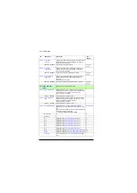
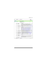
Displays the torque controller limitation status word.
This parameter is read-only.
-
0000h…FFFFh
Torque limitation status word.
1 = 1
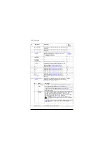
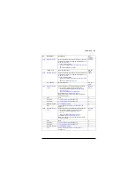
Defines the minimum allowed speed.
WARNING!
This value must not be higher than
In frequency control mode, this limit is not effective.
Make sure the frequency limits (
)
are set appropriately if frequency control is used.
-1500.00 rpm;
-1800.00 rpm
(
b0)
-30000.00
…30000.00 rpm
Minimum allowed speed.
See par.
Defines the maximum allowed speed.
WARNING!
This value must not be lower than
WARNING!
In frequency control mode, this limit is
not effective. Make sure the frequency limits (
and
) are set appropriately if frequency
control is used.
1500.00 rpm;
1800.00 rpm
(
b0)
-30000.00
…30000.00 rpm
Maximum speed.
See par.
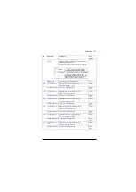
No.
Name/Value
Description
Def/
FbEq16
Bit
Name
Description
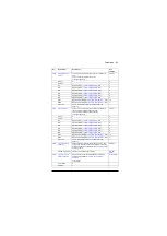
0
Undervoltage
*1 = Intermediate DC circuit undervoltage
1
Overvoltage
*1 = Intermediate DC circuit overvoltage
2
Minimum torque
*1 = Torque is being limited by
3
Maximum torque
*1 = Torque is being limited by
4
Internal current
1 = An inverter current limit (identified by bits 8…11) is active
5
Load angle
(With permanent magnet motors and synchronous reluctance
motors only)
1 = Load angle limit is active, ie. the motor cannot produce any
more torque
6
Motor pullout
(With asynchronous motors only)
1 = Motor pull-out limit is active, ie. the motor cannot produce
any more torque
7
Reserved
8
Thermal
1 = Input current is being limited by the main circuit thermal limit
9
Max current
*1 = Maximum output current (
I
MAX
) is being limited
10
User current
*1 = Output current is being limited by
11
Thermal IGBT
*1 = Output current is being limited by a calculated thermal
current value
12
IGBT overtemperature *1 = Output current is being limited because of estimated IGBT
temperature
13
IGBT overload
*1 = Output current is being limited because of IGBT junction to
case temperature
14…15 Reserved
*Only one out of bits 0…3, and one out of bits 9…13 can be on simultaneously. The bit typically
indicates the limit that is exceeded first.
Summary of Contents for ACS880 ESP
Page 1: ...ABB industrial drives Firmware manual ACS880 PCP ESP control program ...
Page 4: ......
Page 28: ...28 PCP ESP control start up ...
Page 30: ...30 Using the control panel ...
Page 94: ...94 Standard programposi features ...
Page 100: ...100 Default control connections ...
Page 360: ...360 Parameters ...
Page 436: ...436 Fault tracing ...
Page 486: ...486 Control chain diagrams ...
Page 492: ...492 Appendix ESP with step up transformer and sine filter ...
Page 494: ...Contact us www abb com drives www abb com drivespartners 3AXD50000016186 Rev B EN 2015 10 27 ...


