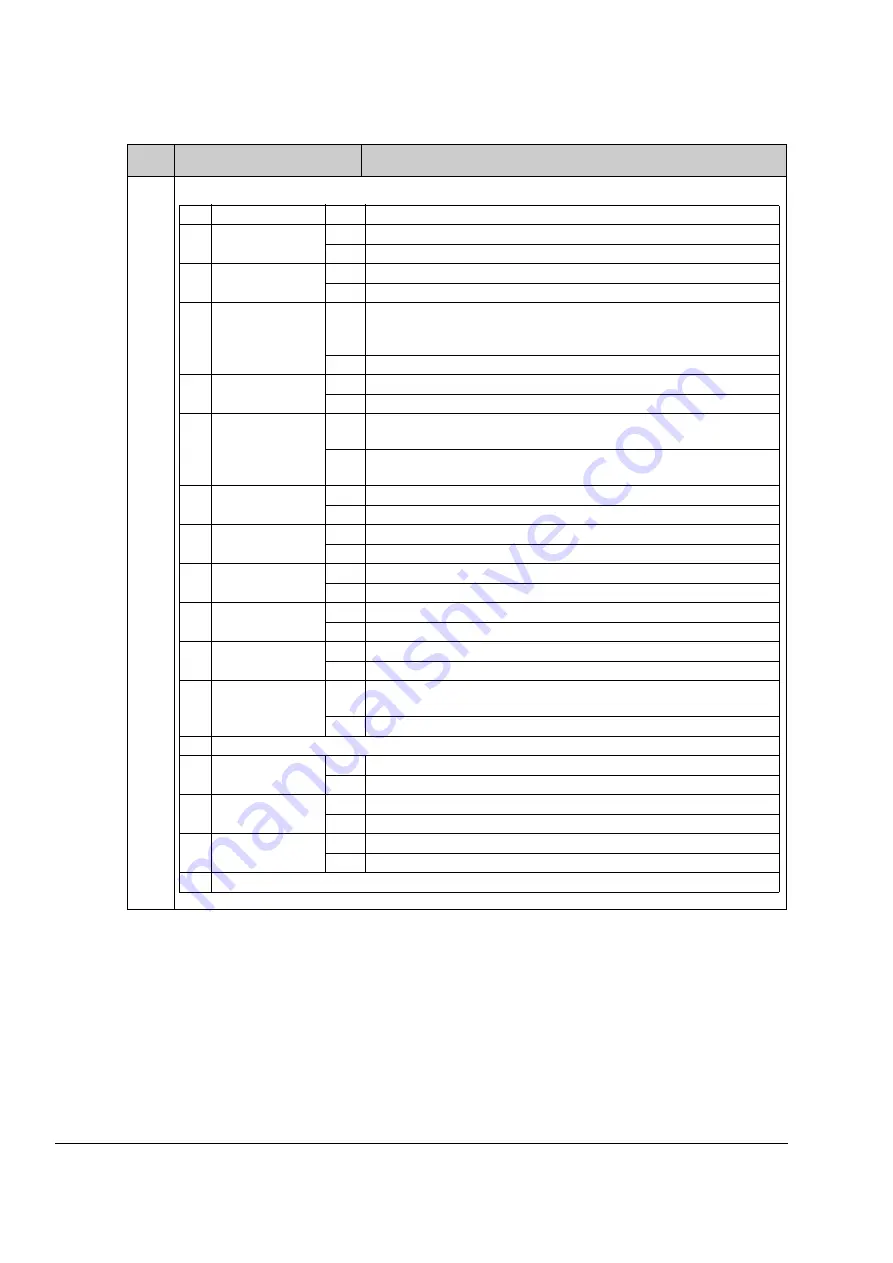
Parameters and firmware blocks
66
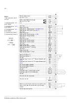
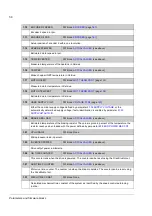
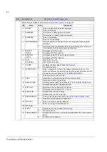
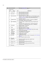
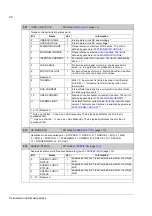
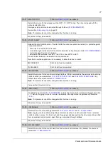
6.02
STATUS WORD 2
FW block:
(page
Status word 2.
Bit
Name
Val.
Information
0
START ACT
1
Drive start command is active.
0
Drive start command is inactive.
1
STOP ACT
1
Drive stop command is active.
0
Drive stop command is inactive.
2
READY RELAY
1
Ready to function: run enable signal on, no fault, emergency stop
signal off, no ID run inhibition. Connected by default to DIO1 by par.
. (Can be freely connected anywhere.)
0
Not ready to function
3
MODULATING
1
Modulating: IGBTs are controlled, i.e. the drive is RUNNING.
0
No modulation: IGBTs are not controlled.
4
REF RUNNING
1
Normal operation is enabled. Running. Drive follows the given
reference.
0
Normal operation is disabled, Drive is not following the given
reference (e.g. in magnetisation phase drive is modulating).
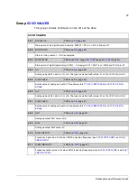
5
JOGGING
1
Jogging function 1 or 2 is active.
0
Jogging function is inactive.
6
OFF1
1
Emergency stop OFF1 is active.
0
Emergency stop OFF1 is inactive.
7
START INH
MASK
1
Maskable (by par.
) start inhibit is active.
0
No start inhibit (maskable)
8
START INH
NOMASK
1
Non-maskable start inhibit is active.
0
No start inhibit (non-maskable)
9
CHRG REL
CLOSED
1
Charging relay is closed.
0
Charging relay is open.
10
STO ACT
1
Safe Torque Off function is active. See parameter
.
0
Safe Torque Off function is inactive.
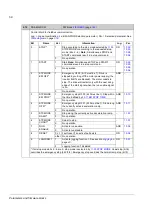
11
Reserved
12
RAMP IN 0
1
Ramp Function Generator input is forced to zero.
0
Normal operation
13
RAMP HOLD
1
Ramp Function Generator output is held.
0
Normal operation
14
RAMP OUT 0
1
Ramp Function Generator output is forced to zero.
0
Normal operation
15
Reserved
Summary of Contents for ACSM1 Series
Page 1: ...ACSM1 Firmware Manual ACSM1 Speed and Torque Control Program...
Page 2: ......
Page 4: ......
Page 12: ...Table of contents 12...
Page 49: ...Drive control and features 49...
Page 282: ...Standard function blocks 282...
Page 306: ...Application program template 306...
Page 312: ...Control chain block diagrams 312...
Page 331: ...331...
Page 332: ...332...
Page 333: ......

