Manual 104-QUAD-8
13
Chapter 5: Programming
The card is an I/O-mapped device that is easily configured from any language and any language can
easily perform quadrature reads. This is especially true if the form of the data is byte or word wide. All
references to the I/O ports would be in absolute port addressing. However, a table could be used to
convert the byte or word data ports to a logical reference.
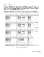
Please refer to the chip-specification for the LS7267 in addition to this user manual for guidance
and information helpful to write device drivers for it (this spec sheet is on the software CD located in
“ChipDocs”), Also, the source code for Windows shows how to write device drivers for this product.
Address
Port Assignment
Operation
Device
Base Address
Channel 1 Data
Read/Write
First LS7267
Base A1
Channel 1 Flag / Command
Read/Write
Base A2
Channel 2 Data
Read/Write
Base A3
Channel 2 Flag / Command
Read/Write
Base A4
Channel 3 Data
Read/Write
Second LS7267
Base A5
Channel 3 Flag / Command
Read/Write
Base A6
Channel 4 Data
Read/Write
Base A7
Channel 4 Flag / Command
Read/Write
Base A8
Channel 5 Data
Read/Write
Third LS7267
Base A9
Channel 5 Flag / Command
Read/Write
Base AA
Channel 6 Data
Read/Write
Base AB
Channel 6 Flag / Command
Read/Write
Base AC
Channel 7 Data
Read/Write
Fourth LS7267
Base AD
Channel 7 Flag / Command
Read/Write
Base AE
Channel 8 Data
Read/Write
Base AF
Channel 8 Flag / Command
Read/Write
Base A10
Interrupt Status Register
Read Only
CPLD
Base A11
Channel Operation Register
Read/Write
Base A12
Index/Interrupt Register
Read/Write
Base A13
Reserved for Factory Use
N/A
Base A14
Reserved for Factory Use
N/A
Base A15
Reserved for Factory Use
N/A
Base A16
Index Input Levels
Read Only
Base A17
Differential Encoder Cable Status
Read/Write
Base A18
CPLD Revision
Read Only
Base A19 t1F
Reserved for Factory Use
N/A
Table 5-1:
Base Address Map

