Contents MSX-E1701:
Digital
I/O
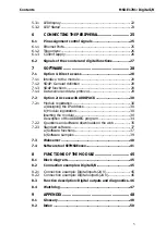
LED display ..........................................................................22
LED “Status”..........................................................................23
CONNECTING THE PERIPHERAL...........................25
Pin assignment control signals ......................................25
Ethernet Ports .......................................................................25
Trigger/sync..........................................................................26
Current supply .....................................................................26
Signals of the counter and digital functions..................27
SOFTWARE .........................................................28
Option 1: Direct access .................................................28
Interface to the module ......................................................28
SOAP: General definition .....................................................28
SOAP functions ....................................................................29
Data server and data protocol............................................29
Option 2: Access with ADDIPACK ...................................30
Module registration..............................................................30
a) Assigning the IP address ..................................................30
b) Module registration..........................................................30
Inserting the module............................................................30
Description of the ADDIREG program ..................................34
Questions and software downloads on the web .................35
Standard software ...............................................................37
a) Software functions ...........................................................37
b) Software samples ............................................................39
Webserver ......................................................................40
Software tool SETMSXExxxx.............................................41
FUNCTIONS OF THE MODULE ..............................45
Block diagram................................................................45
Connection examples: Digital I/O..................................45
Connection example: Digital inputs (24 V) ..........................45
Connection example: Digital outputs (24 V)........................46
Function description: Digital outputs and diagnostics..46
Watchdog.......................................................................47
APPENDIX ..........................................................48
Glossary .........................................................................48
Index ..............................................................................50
5

