ESP32-SL specification V1.0
C
opyright © 2019 Shenzhen Ai-Thinker Technology Co., Ltd All Rights Reserved
XIII
34
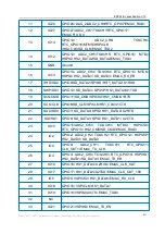
RXD0
GPIO3/U0RXD/ CLK_OUT2
35
TXD0
GPIO1/ U0TXD/ CLK_OUT3/ EMAC_RXD2
36
IO22
GPIO22/ VSPIWP/ U0RTS/ EMAC_TXD1
37
IO23
GPIO23/ VSPID/ HS1_STROBE
38
GND
Ground
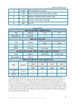
Strapping PIN
Built-in LDO
(
VDD_SDIO
)
Voltage
PIN
Default
3.3V
1.8V
MTDI/GPIO12
Pull down
0
1
System startup mode
PIN
Default
SPI Flash startup
mode
Download startup
mode
GPIO0
Pull up
1
0
GPIO2
Pull down
Non-sense
0
During system startup, U0TXD outputs log print information
PIN
Default
U0TXD Flip
U0TXD still
MTDO/GPIO15
Pull up
1
0
SDIO slave signal input and output timing
PIN
Default
Falling edge
output
Falling edge
input
Falling edge
input
Rising edge
output
Rising edge
input
Falling edge
output
Rising edge
input
Rising edge
output
MTDO/GPI
O15
Pull up
0
0
1
1
GPIO5
Pull up
0
1
0
1
Note: ESP32 has 6 strapping pins in total, and the software can read the value of these 6 bits in the register
"GPIO_STRAPPING". During the chip power-on reset process, the strapping pins are sampled and stored in the
latches. The latches are "0" or "1" and remain until the chip is powered off or turned off. Each strapping pin is
connected to internal pull-up/pull-down. If a strapping pin is not connected or the connected external line is in a high
impedance state, the internal weak pull-up/pull-down will determine the default value of the strapping pin input level.
To change the value of the strapping bits, the user can apply external pull-down/pull-up resistors, or apply the GPIO
of the host MCU to control the level of the strapping pins at power-on reset of ESP32. After reset, the strapping pin
has the same function as the normal pin.

