background image

ESP32-SL specification V1.0

XX

channel. 
Additional testing, Part 15 Subpart B disclaimer   
The  module without  unintentional-radiator  digital  circuit,  so  the  module  does  not required  an 
evaluation by FCC Part 15 Subpart B. The host should be evaluated by the FCC Subpart B.   
ATTENTION   
This device is intended only for OEM integrators under the following conditions: 1)  The  antenna 
must be installed such that 20 cm is maintained between the antenna and users, and 
2) This device and its antenna(s) must not be co

located with any other transmitters except in

accordance with FCC multi

transmitter product procedures. Referring to the multi

transmitter

policy, multiple transmitter(s) and module(s) can be operated simultaneously without C2P.
3) For all products market in US, OEM has to limit the Operating Frequency: 2400 ~2500MHz
by supplied firmware programming tool. OEM shall not supply any tool or info to the end

user

regarding to Regulatory Domain change.

USERS MANUAL OF THE END PRODUCT:   
In the user manual of the end product, the end user has to be informed to keep at least 20cm 
separation with the antenna while this end product is installed and operated. The end user has to 
be informed that the FCC radio

frequency exposure guidelines for an uncontrolled environment 

can be satisfied. The end user has to also be informed that any changes or modifications not 
expressly approved by the manufacturer could void the user's authority to operate this 
equipment.   
If the size of the end product is smaller than 8x10cm, then additional FCC part 15.19 statement is 
required to be available in the users manual: This device complies with Part 15 of FCC rules. 
Operation is subject to the following two conditions: 
(1) this device may not cause harmful interference and
(2) this device must accept any interference received, including interference that may cause
undesired operation.

FCC WARNING   
This device complies with part 15 of the FCC Rules. Operation is subject to the following two 
conditions: 
Any changes or modifications not expressly approved by the party responsible for compliance 
could void the user's authority to operate the equipment.   
NOTE: This equipment has been tested and found to comply with the limits for a Class B digital 
device, pursuant to Part 15 of the FCC Rules. These limits are designed to provide reasonable 
protection against harmful interference in a residential installation. This equipment generate, 
uses and can radiate radio frequency energy and, if not installed and used in accordance with the 
instructions, may cause harmful interference to radio communications. However, there is no 
guarantee that interference will not occur in a particular installation.   
If this equipment does cause harmful interference to radio or television reception, which can be 
determined by turning the equipment off and on, the user is encouraged to try to correct the 
interference by one or more of the following measures:   
-- Reorient or relocate the receiving antenna.  
-- Increase the separation between the equipment and receiver.  

-- Connect the equipment into an outlet on a circuit different from that to which the receiver is 
connected.  
-- Consult the dealer or an experienced radio/TV technician for help. 

Summary of Contents for ESP32-SL

Page 1: ...ESP32 SL specification V1 0 Copyright 2020 Shenzhen Ai Thinker Technology Co Ltd All Rights Reserved I ESP32 SL specification Version V1 0 Copyright 2020...

Page 2: ...he test data obtained in this article are all obtained by Enxin Lab s laboratory tests and the actual results may be slightly different The Wi Fi Alliance member logo is owned by the Wi Fi Alliance Al...

Page 3: ...ication V1 0 Copyright 2020 Shenzhen Ai Thinker Technology Co Ltd All Rights Reserved III Formulation Revision Abolition of CV Version Date Formulation Revision Maker Verify V1 0 2019 11 1 First formu...

Page 4: ...Ai Thinker Technology Co Ltd All Rights Reserved IV CONTENT 1 PRODUCT OVERVIEW V 2 ELECTRONICS PARAMETER VIII 3 DIMENSION X 4 PIN DEFINITION XI 5 SCHEMATIC DIAGRAM XIV 6 DESIGN GUIDE XV 7 REFLOW SOLDE...

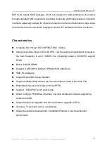
Page 5: ...applications It is an IoT application Ideal solution The core of this module is the ESP32 S0WD chip which is scalable and adaptive The user can cut off the power of the CPU and use the low power cons...

Page 6: ...e Using low power single core 32 bit CPU can be used as an application processor the main frequency is up to 160MHz the computing power is 200 MIPS support RTOS Built in 520 KB SRAM Support UART SPI S...

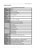
Page 7: ...tore environment 40 125 90 RH Power supply Voltage 3 0V 3 6V current 500mA Power consumption Wi Fi TX 13dBm 21dBm 160 260mA BT TX 120mA Wi Fi RX 80 90mA BT RX 80 90mA Modem sleep 5 10mA Light sleep 0...

Page 8: ...2400 2483 5 MHz Output power In 11n mode PA output power is 13 2 dBm In 11g mode PA output power is 14 2 dBm In 11b mode PA output power is 17 2 dBm Receiving sensitivity CCK 1 Mbps 98 dBm CCK 11 Mbps...

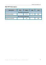
Page 9: ...ight 2019 Shenzhen Ai Thinker Technology Co Ltd All Rights Reserved IX BLE RF Performance Description Min Typical Max Unit Sending characteristics Sending sensitivity 7 5 10 dBm Receiving characterist...

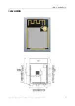
Page 10: ...ESP32 SL specification V1 0 Copyright 2019 Shenzhen Ai Thinker Technology Co Ltd All Rights Reserved X 3 DIMENSION...

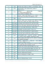
Page 11: ...iption No Name Function description 1 GND Ground 2 3V3 Power supply 3 EN Enable chip high level is effective 4 SENSOR_ VP GPI36 SENSOR_VP ADC_H ADC1_CH0 RTC_GPIO0 5 SENSOR_ VN GPI39 SENSOR_VN ADC1_CH3...

Page 12: ...TA3 SPIWP HS1_DATA3 U1TXD 19 SCS CMD GPIO11 SD_CMD SPICS0 HS1_CMD U1RTS 20 SCK CLK GPIO6 SD_CLK SPICLK HS1_CLK U1CTS 21 SDO SD0 GPIO7 SD_DATA0 SPIQ HS1_DATA0 U2RTS 22 SDI SD1 GPIO8 SD_DATA1 SPID HS1_D...

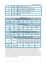
Page 13: ...Falling edge output Rising edge input Rising edge output MTDO GPI O15 Pull up 0 0 1 1 GPIO5 Pull up 0 1 0 1 Note ESP32 has 6 strapping pins in total and the software can read the value of these 6 bit...

Page 14: ...ESP32 SL specification V1 0 Copyright 2019 Shenzhen Ai Thinker Technology Co Ltd All Rights Reserved XIV 5 SCHEMATIC DIAGRAM...

Page 15: ...rboard and the edge of the motherboard digs out an area at the position of the antenna 2 In order to meet the performance of the onboard antenna it is forbidden to place metal parts around the antenna...

Page 16: ...Help both EMI and ESD 2 For the up and down of the special IO port please refer to the instruction manual of the specification which will affect the startup configuration of the module 3 The IO port...

Page 17: ...ESP32 SL specification V1 0 Copyright 2019 Shenzhen Ai Thinker Technology Co Ltd All Rights Reserved XVII 7 REFLOW SOLDERING CURVE FCC ID...

Page 18: ...SL is taping 9 CONTACT US Web https www ai thinker com Development DOCS https docs ai thinker com Official forum http bbs ai thinker com Sample purchase http ai thinker en alibaba com Business sales a...

Page 19: ...not recommended to conduct heat dissipation through air or screw column heat conduction 5 UART1 and UART2 are serial ports with the same priority The port which receives commands returns information...

Page 20: ...r than 8x10cm then additional FCC part 15 19 statement is required to be available in the users manual This device complies with Part 15 of FCC rules Operation is subject to the following two conditio...

Reviews: